“MY-IMX6-MB140 硬件介绍”的版本间的差异
来自明远智睿的wiki
| 第4行: | 第4行: | ||
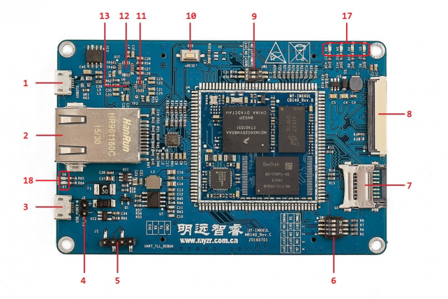
[[文件:myimx6_mb140_1.1.0.1.png|642px]] | [[文件:myimx6_mb140_1.1.0.1.png|642px]] | ||
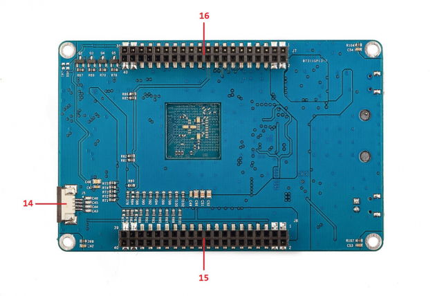
== '''背面图(bottom view)''' == | == '''背面图(bottom view)''' == | ||
| − | [[文件: | + | [[文件:myimx6_mb140_1.2.0.1.png|642px]] |
== '''图示模块(graphic module)''' == | == '''图示模块(graphic module)''' == | ||
{| class="wikitable" | {| class="wikitable" | ||
| 第15行: | 第15行: | ||
|- | |- | ||
|1 | |1 | ||
| − | | | + | |USB OTG |
| − | | | + | |MFG Tool烧录口及USB OTG<br>(MFG Tool burning port and USB OTG) |
|Micro USB | |Micro USB | ||
| − | | | + | |J4 |
|- | |- | ||
|2 | |2 | ||
| − | | | + | |ENET |
| − | | | + | |10/100-Mbps以太网<br>(10/100-Mbps ethernet) |
| − | | | + | |RJ-45 |
| − | | | + | |P1 |
|- | |- | ||
|3 | |3 | ||
| − | | | + | |5V_IN |
| − | | | + | |电源输入<br>(power in) |
| − | | | + | |Micro USB |
| − | | | + | |J3 |
|- | |- | ||
|4 | |4 | ||
| − | | | + | |5V_IN |
| − | | | + | |电源输入<br>(power in) |
| − | | | + | |单排插针(2针)<br>(single row pin(2pins)) |
| − | | | + | |J2 |
|- | |- | ||
|5 | |5 | ||
| − | | | + | |DEBUG UART |
| − | | | + | |调试串口<br>(debug serial port) |
| − | | | + | |单排插针(4针)<br>(single row pin(4 pins)) |
| − | | | + | |J1 |
|- | |- | ||
|6 | |6 | ||
| − | | | + | |BOOT Device |
| − | | | + | |启动设备选择<br>(boot device option) |
| − | | | + | |拨码开关(4位)<br>(dial switch(4bit)) |
|SW1 | |SW1 | ||
|- | |- | ||
| 第54行: | 第54行: | ||
|TF卡<br>(TF card) | |TF卡<br>(TF card) | ||
|TF卡座(翻盖式)<br>(TF booth(flip-type)) | |TF卡座(翻盖式)<br>(TF booth(flip-type)) | ||
| − | | | + | |U2 |
|- | |- | ||
|8 | |8 | ||
| 第60行: | 第60行: | ||
|LCD显示接口<br>(LCD display interface) | |LCD显示接口<br>(LCD display interface) | ||
|FPC插座(翻盖式,40 Pin)<br>(FPC socket(flip-type,40 Pins)) | |FPC插座(翻盖式,40 Pin)<br>(FPC socket(flip-type,40 Pins)) | ||
| − | | | + | |U1 |
|- | |- | ||
|9 | |9 | ||
| − | | | + | |BOOT MODE |
| − | | | + | |启动模式选择<br>(boot mode option) |
| − | | | + | |拨码开关(2位)<br>(dial switch(2 bit)) |
| − | | | + | |SW2 |
|- | |- | ||
|10 | |10 | ||
| + | |RESET | ||
| + | |复位按钮<br>(reset button) | ||
| + | |按键(两脚)<br>(key(2 pins)) | ||
| + | |SW3 | ||
| + | |- | ||
| + | |11 | ||
| + | |FXLS8471Q | ||
| + | |加速度传感器<br>(acceleration sensor) | ||
| + | |无<br>(none) | ||
| + | |U8 | ||
| + | |- | ||
| + | |12 | ||
| + | |FXAS21002CQ | ||
| + | |3轴数字陀螺仪<br>(3D digital gyroscope) | ||
| + | |无<br>(none) | ||
| + | |U10 | ||
| + | |- | ||
| + | |13 | ||
| + | |MAG3110 | ||
| + | |3轴地磁传感器<br>(3D magnetic sensor) | ||
| + | |无<br>(none) | ||
| + | |U9 | ||
| + | |- | ||
| + | |14 | ||
| + | |TS | ||
| + | |电阻触摸屏接口<br>(resistance touch interface) | ||
| + | |PFC插座(抽屉式,4 Pin)<br>(PFC socket(drawer-type,4 Pin)) | ||
| + | |J5 | ||
| + | |- | ||
| + | |15 | ||
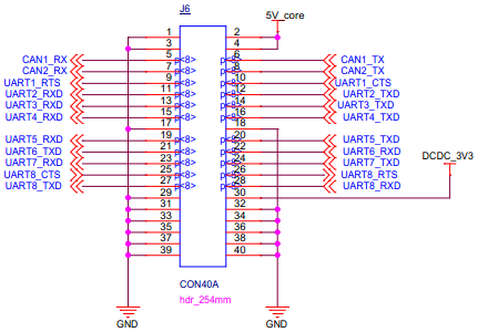
| + | |J6 | ||
| + | |功能插座<br>(function socket) | ||
| + | |双排插座(40 Pin)<br>(double row socket(40 Pins)) | ||
| + | |J3 | ||
| + | |- | ||
| + | |16 | ||
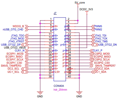
| + | |J7 | ||
| + | |功能插座<br>(function socket) | ||
| + | |双排插座(40 Pin)<br>(double row socket(40 Pins)) | ||
| + | |SW1 | ||
| + | |- | ||
| + | |17 | ||
|USER LIGHT | |USER LIGHT | ||
| − | |用户LED灯<br>(user LED light) | + | |用户LED灯<br>(user LED light) |
| − | |LED灯(4个)<br>(LED light (4 units)) | + | |LED灯(4个)<br>(LED light (4 units)) |
| − | | | + | |D* |
|- | |- | ||
| − | | | + | |18 |
|POWER LIGHT | |POWER LIGHT | ||
| − | |电源指示灯<br>(power indication light) | + | |电源指示灯<br>(power indication light) |
| − | |LED灯(2个)<br>(LED light (2 units)) | + | |LED灯(2个)<br>(LED light (2 units)) |
| − | | | + | |D* |
| − | |||
| − | |||
|} | |} | ||
= '''接口功能(interface function)''' = | = '''接口功能(interface function)''' = | ||
---- | ---- | ||
| − | == ''' | + | == '''USB OTG''' == |
{| class="wikitable" | {| class="wikitable" | ||
|- | |- | ||
| 第95行: | 第135行: | ||
|- | |- | ||
|1 | |1 | ||
| − | | | + | |USB OTG |
| − | | | + | |MFG Tool烧录口及USB OTG<br>(MFG Tool burning port and USB OTG) |
|Micro USB | |Micro USB | ||
| − | | | + | |J4 |
|} | |} | ||
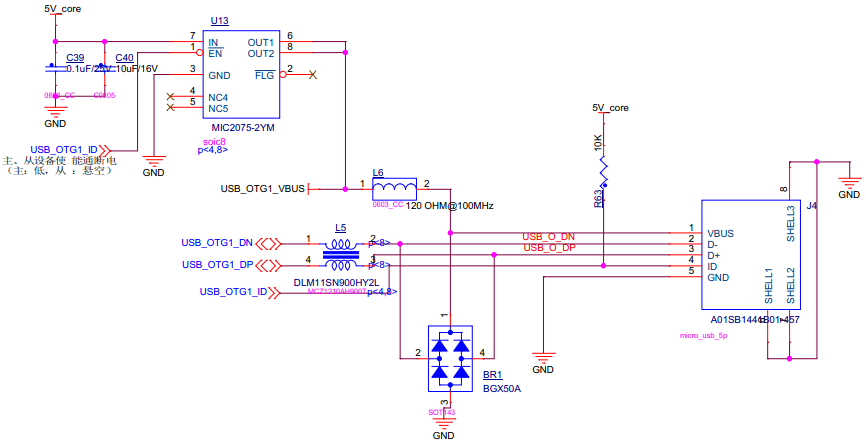
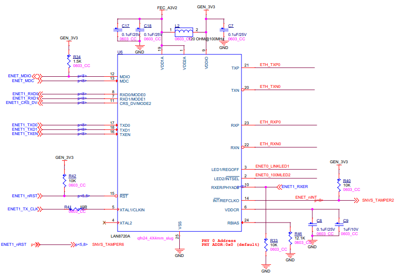
* 原理图及信号<br> | * 原理图及信号<br> | ||
<span style="background:#CCCCCC">schematic and signal</span><br> | <span style="background:#CCCCCC">schematic and signal</span><br> | ||
| − | [[文件: | + | [[文件:myimx6_mb140_2.1.0.1.png]] |
{| class="wikitable" | {| class="wikitable" | ||
|- | |- | ||
| 第123行: | 第163行: | ||
|4 | |4 | ||
|ID | |ID | ||
| − | | | + | |USB_OTG1_ID |
|- | |- | ||
|5 | |5 | ||
| 第130行: | 第170行: | ||
|} | |} | ||
| − | == ''' | + | == '''ENET''' == |
| − | |||
| − | |||
| − | |||
| − | |||
{| class="wikitable" | {| class="wikitable" | ||
| − | |||
|- | |- | ||
!标号<br>(no.) | !标号<br>(no.) | ||
| − | |||
!接口<br>(interface) | !接口<br>(interface) | ||
| − | |||
!功能<br>(function) | !功能<br>(function) | ||
| − | |||
!接口形式<br>(interface form) | !接口形式<br>(interface form) | ||
| − | |||
!丝印<br>(silk screen) | !丝印<br>(silk screen) | ||
|- | |- | ||
|2 | |2 | ||
| − | + | |ENET | |
| − | | | + | |10/100-Mbps以太网<br>(10/100-Mbps ethernet) |
| − | + | |RJ-45 | |
| − | | | + | |P1 |
| − | |||
| − | | | ||
| − | |||
| − | | | ||
|} | |} | ||
| − | + | * 接口图及信号<br> | |
| − | * | + | <span style="background:#CCCCCC">interface map and signal</span><br> |
| − | <span style="background:#CCCCCC"> | + | [[文件:myimx6_mb140_2.2.0.1.png]] |
| − | [[文件: | ||
{| class="wikitable" | {| class="wikitable" | ||
|- | |- | ||
| − | ! | + | !接口引脚序号<br>(interface pin order no.) |
!功能信号名称<br>(name of function signal) | !功能信号名称<br>(name of function signal) | ||
| − | ! | + | |rowspan=7| |
| + | !接口引脚序号<br>(interface pin order no.) | ||
| + | !功能信号名称<br>(name of function signal) | ||
|- | |- | ||
|1 | |1 | ||
| − | | | + | |LED_Y+ |
| − | | | + | |
| + | |7 | ||
| + | |RD+ | ||
|- | |- | ||
|2 | |2 | ||
| − | | | + | |LED_Y- |
| − | | | + | |
| + | |8 | ||
| + | |RD- | ||
|- | |- | ||
|3 | |3 | ||
| − | | | + | |TD- |
| − | | | + | |
| − | + | |9 | |
| − | + | |NC | |
|- | |- | ||
|4 | |4 | ||
| − | | | + | |TD+ |
| − | | | + | |
| + | |10 | ||
| + | |GND | ||
| + | |- | ||
| + | |5 | ||
| + | |MTD | ||
| + | |||
| + | |11 | ||
| + | |LED_G- | ||
| + | |- | ||
| + | |6 | ||
| + | |MRD | ||
| + | |||
| + | |12 | ||
| + | |LED_G+ | ||
|} | |} | ||
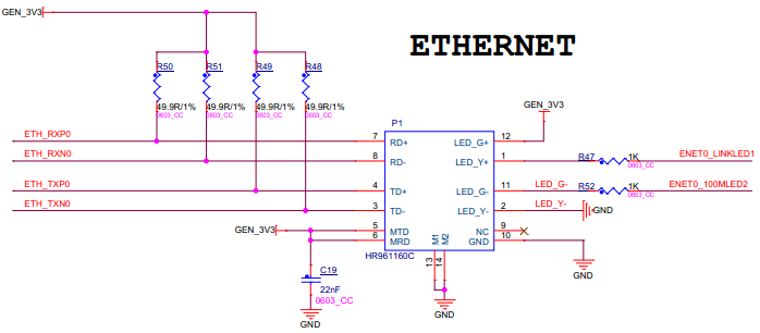
| − | + | * 原理图及信号<br> | |
| − | = | + | <span style="background:#CCCCCC">schematic and signal</span><br> |
| + | [[文件:myimx6_mb140_2.2.0.2.png]] | ||
{| class="wikitable" | {| class="wikitable" | ||
|- | |- | ||
| − | ! | + | !使用的引脚<br>(pin used) |
| − | ! | + | !引脚功能<br>(pin function) |
| − | ! | + | |rowspan=7| |
| − | ! | + | !使用的引脚<br>(pin used) |
| − | + | !引脚功能<br>(pin function) | |
| + | |- | ||
| + | |ENET_MDIO | ||
| + | |MDIO | ||
| + | |||
| + | |ENET_MDC | ||
| + | |MDC | ||
| + | |- | ||
| + | |ENET1_RXD0 | ||
| + | |RXD0/MODE0 | ||
| + | |||
| + | |ENET1_RXD1 | ||
| + | |RXD1/MODE1 | ||
| + | |- | ||
| + | |ENET1_TXD0 | ||
| + | |TXD0 | ||
| + | |||
| + | |ENET1_TXD1 | ||
| + | |TXD1 | ||
| + | |- | ||
| + | |ENET1_CRS_DV | ||
| + | |CRS_DV/MODE2 | ||
| + | |||
| + | |ENET1_TXEN | ||
| + | |TXEN | ||
| + | |- | ||
| + | |ENET1_TX_CLK | ||
| + | |XTAL1/CLKIN | ||
| + | |||
| + | |ENET1_RXER | ||
| + | |RXER/PHYAD0 | ||
|- | |- | ||
| − | | | + | |ENET1_nRST |
| − | | | + | |RST |
| − | + | ||
| − | | | + | |SNVS_TAMPER2 |
| − | | | + | |INT/REFCLKO |
|} | |} | ||
| − | + | ||
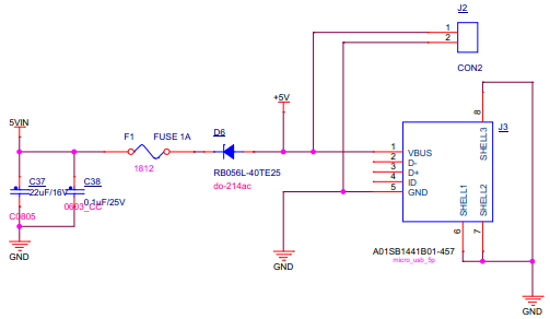
| − | <span style="background:#CCCCCC"> | + | == '''5V_IN''' == |
| − | + | MY-IMX6-MB140可接受的输入电压是5V,提供两种电源输入接口。一个是单排插针(2针),一种是Micro USB。两种电源输入方式任选一种,需要注意是的USB的供电能力。<br> | |
| − | + | <span style="background:#CCCCCC">The acceptable voltage input is 5V for MY-IMX6-MB140,and It provides two types of power input interface.One is single row pin,one is Micro USB.You can choose one of them.But pay attention to the power supply capacity</span><br> | |
| − | |||
| − | |||
| − | |||
{| class="wikitable" | {| class="wikitable" | ||
| + | |||
|- | |- | ||
!标号<br>(no.) | !标号<br>(no.) | ||
| + | |||
!接口<br>(interface) | !接口<br>(interface) | ||
| + | |||
!功能<br>(function) | !功能<br>(function) | ||
| + | |||
!接口形式<br>(interface form) | !接口形式<br>(interface form) | ||
| + | |||
!丝印<br>(silk screen) | !丝印<br>(silk screen) | ||
| + | |- | ||
| + | |3 | ||
| + | |||
| + | |5V_IN | ||
| + | |||
| + | |电源输入<br>(power in) | ||
| + | |||
| + | |Micro USB | ||
| + | |||
| + | |J3 | ||
|- | |- | ||
|4 | |4 | ||
| − | | | + | |
| − | | | + | |5V_IN |
| − | | | + | |
| − | | | + | |电源输入<br>(power in) |
| + | |||
| + | |单排插针(2针)<br>(single row pin(2pins)) | ||
| + | |||
| + | |J2 | ||
|} | |} | ||
| + | |||
* 原理图及信号<br> | * 原理图及信号<br> | ||
<span style="background:#CCCCCC">schematic and signal</span><br> | <span style="background:#CCCCCC">schematic and signal</span><br> | ||
| − | [[文件: | + | [[文件:myimx6_mb140_2.3.0.1.png]] |
{| class="wikitable" | {| class="wikitable" | ||
| + | |||
|- | |- | ||
| − | !接口序号<br>(interface order number) | + | !colspan=2|J2 |
| − | + | ||
| + | |rowspan=4| | ||
| + | !colspan=2|J3 | ||
| + | |- | ||
| + | |接口序号<br>(interface order number) | ||
| + | |引脚功能<br>(pin function) | ||
| + | |接口序号<br>(interface order number) | ||
| + | |引脚功能<br>(pin function) | ||
|- | |- | ||
|1 | |1 | ||
| − | | | + | |+5V输入<br>(+5V input) |
| + | |1 | ||
| + | |+5V输入<br>(+5V input) | ||
|- | |- | ||
|2 | |2 | ||
| − | | | + | |GND |
| − | | | + | |5 |
| − | |||
| − | |||
| − | |||
| − | |||
|GND | |GND | ||
|} | |} | ||
| − | == ''' | + | |
| + | == '''DEBUG UART''' == | ||
{| class="wikitable" | {| class="wikitable" | ||
|- | |- | ||
| 第255行: | 第356行: | ||
|- | |- | ||
|5 | |5 | ||
| − | | | + | |DEBUG UART |
| − | | | + | |调试串口<br>(debug serial port) |
| − | | | + | |单排插针(4针) |
| − | | | + | |J1 |
|} | |} | ||
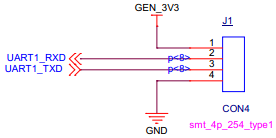
| − | * | + | * 原理图及信号<br> |
| − | <span style="background:#CCCCCC">schematic and | + | <span style="background:#CCCCCC">schematic and signal</span><br> |
| − | [[文件: | + | [[文件:myimx6_mb140_2.4.0.1.png]] |
{| class="wikitable" | {| class="wikitable" | ||
|- | |- | ||
| − | ! | + | !接口序号<br>(interface order number) |
| − | ! | + | !引脚功能<br>(pin function) |
| + | |rowspan=3| | ||
| + | !接口序号<br>(interface order number) | ||
| + | !引脚功能<br>(pin function) | ||
|- | |- | ||
| − | | | + | |1 |
| − | | | + | |GEN_3V3 |
| + | |||
| + | |2 | ||
| + | |UART1_RXD | ||
|- | |- | ||
| − | | | + | |4 |
| − | | | + | |GND |
| + | |||
| + | |3 | ||
| + | |UART1_TXD | ||
|} | |} | ||
| − | == ''' | + | == '''BOOT Device''' == |
{| class="wikitable" | {| class="wikitable" | ||
|- | |- | ||
| 第286行: | 第396行: | ||
|- | |- | ||
|6 | |6 | ||
| − | | | + | |BOOT Device |
| − | | | + | |启动设备选择<br>(boot device option) |
| − | | | + | |拨码开关(4位)<br>(dial switch(4 bit)) |
|SW1 | |SW1 | ||
|} | |} | ||
| − | * | + | |
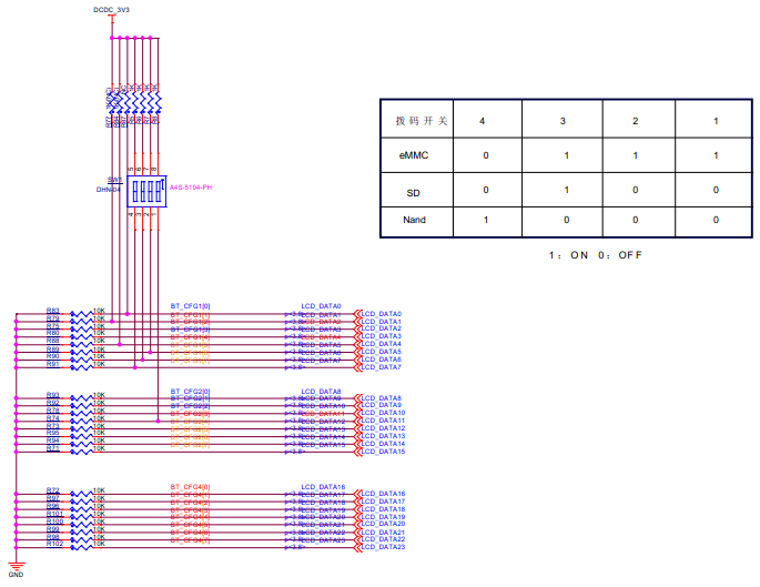
| − | <span style="background:#CCCCCC">schematic</span><br> | + | * 原理图及启动设备选择<br> |
| − | [[文件: | + | <span style="background:#CCCCCC">schematic and boot device option</span><br> |
| + | [[文件:myimx6_mb140_2.5.0.1.png]] | ||
== '''TF''' == | == '''TF''' == | ||
| 第308行: | 第419行: | ||
|TF卡<br>(TF card) | |TF卡<br>(TF card) | ||
|TF卡座(翻盖式)<br>(TF socket(flip type)) | |TF卡座(翻盖式)<br>(TF socket(flip type)) | ||
| − | | | + | |U2 |
|} | |} | ||
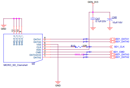
* 原理图及信号<br> | * 原理图及信号<br> | ||
<span style="background:#CCCCCC">schematic and signal</span><br> | <span style="background:#CCCCCC">schematic and signal</span><br> | ||
| − | [[文件: | + | [[文件:myimx6_mb140_2.6.0.1.png]] |
| + | {| class="wikitable" | ||
| + | |- | ||
| + | !接口序号<br>(interface order number) | ||
| + | !引脚功能<br>(pin function) | ||
| + | !使用的信号<br>(signal used) | ||
| + | |rowspan=7| | ||
| + | !接口序号<br>(interface order number) | ||
| + | !引脚功能<br>(pin function) | ||
| + | !使用的信号<br>(signal used) | ||
| + | |- | ||
| + | |1 | ||
| + | |DATA2 | ||
| + | |SD1_DATA2 | ||
| + | |||
| + | |7 | ||
| + | |DATA0 | ||
| + | |SD1_DATA0 | ||
| + | |- | ||
| + | |2 | ||
| + | |DATA3/CD | ||
| + | |SD1_DATA3 | ||
| + | |||
| + | |8 | ||
| + | |DATA1 | ||
| + | |SD1_DATA1 | ||
| + | |- | ||
| + | |3 | ||
| + | |CMD | ||
| + | |SD1_CMD | ||
| + | |||
| + | |9 | ||
| + | |SHELD_1 | ||
| + | |GND | ||
| + | |- | ||
| + | |4 | ||
| + | |VDD | ||
| + | |GEN_3V3 | ||
| + | |||
| + | |10 | ||
| + | |SHELD_2 | ||
| + | |GND | ||
| + | |- | ||
| + | |5 | ||
| + | |CLK | ||
| + | |SD1_CLK | ||
| + | |||
| + | |11 | ||
| + | |SHELD_3 | ||
| + | |GND | ||
| + | |- | ||
| + | |6 | ||
| + | |VSS | ||
| + | |GND | ||
| + | |||
| + | |12 | ||
| + | |SHELD_4 | ||
| + | |GND | ||
| + | |} | ||
== '''LCD DISPLAY()''' == | == '''LCD DISPLAY()''' == | ||
| 第328行: | 第497行: | ||
|LCD显示接口<br>(LCD display interface) | |LCD显示接口<br>(LCD display interface) | ||
|FPC插座(翻盖式,40 Pin)<br>(EPC socket(flip type,40 pins)) | |FPC插座(翻盖式,40 Pin)<br>(EPC socket(flip type,40 pins)) | ||
| − | | | + | |U1 |
|} | |} | ||
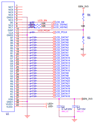
* 显示原理及信号<br> | * 显示原理及信号<br> | ||
<span style="background:#CCCCCC">schematic and signal</span><br> | <span style="background:#CCCCCC">schematic and signal</span><br> | ||
| − | [[文件: | + | [[文件:myimx6_mb140_2.7.0.1.png]] |
{| class="wikitable" | {| class="wikitable" | ||
|- | |- | ||
| + | !接口序号<br>(interface order number) | ||
| + | !引脚功能<br>(pin function) | ||
| + | !使用的信号<br>(signal used) | ||
| + | |rowspan=9| | ||
!接口序号<br>(interface order number) | !接口序号<br>(interface order number) | ||
!引脚功能<br>(pin function) | !引脚功能<br>(pin function) | ||
!使用的信号<br>(signal used) | !使用的信号<br>(signal used) | ||
|- | |- | ||
| − | |1 | + | |1:4,6 |
| − | | | + | |NC* |
| + | |NC | ||
| + | |||
| + | |13:20 | ||
| + | |B7:0 | ||
| + | |LCD_DATA7:0 | ||
| + | |- | ||
| + | |5 | ||
| + | |GND3 | ||
|GND | |GND | ||
| + | |||
| + | |21:28 | ||
| + | |G7:0 | ||
| + | |LCD_DATA15:8 | ||
|- | |- | ||
| − | | | + | |7 |
| − | | | + | |DE |
| − | | | + | |LCD_DE |
| + | |||
| + | |29:36 | ||
| + | |B7:0 | ||
| + | |LCD_DATA23:16 | ||
|- | |- | ||
|8 | |8 | ||
| − | | | + | |NC2 |
| − | | | + | |LCD_VSYNC |
| − | |- | + | |
| + | |37 | ||
| + | |VDD | ||
| + | |GEN_3V3 | ||
| + | |- | ||
|9 | |9 | ||
| − | | | + | |NC1 |
| − | | | + | |LCD_HSYNC |
| + | |||
| + | |38 | ||
| + | |GND1 | ||
| + | |GND | ||
|- | |- | ||
|10 | |10 | ||
| − | | | + | |DISP |
| − | | | + | |GEN_3V3 |
| + | |||
| + | |39 | ||
| + | |VLED+ | ||
| + | |LED+ | ||
|- | |- | ||
|11 | |11 | ||
| − | | | + | |CLK |
| − | | | + | |LCD_PCLK |
| + | |||
| + | |40 | ||
| + | |VLED- | ||
| + | |LED- | ||
|- | |- | ||
| − | | | + | |12 |
| − | | | + | |GND2 |
| − | | | + | |GND |
| − | + | ||
| − | + | | | |
| − | + | | | |
| − | + | | | |
| − | |||
| − | |||
| − | |||
| − | |||
| − | |||
| − | |||
| − | |||
| − | |||
| − | |||
| − | |||
| − | |||
| − | |||
| − | |||
| − | |||
| − | |||
| − | |||
| − | |||
| − | |||
| − | |||
| − | |||
| − | |||
| − | | | ||
| − | | | ||
| − | | | ||
|} | |} | ||
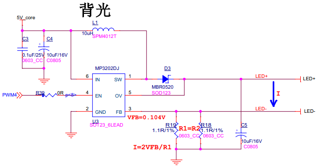
| + | * 背光原理<br> | ||
| + | <span style="background:#CCCCCC">backlight Schematic</span><br> | ||
| + | [[文件:myimx6_mb140_2.7.0.2.png]] | ||
| + | * 背光控制信号<br> | ||
| + | <span style="background:#CCCCCC">backlight control signal</span><br> | ||
| + | PWM4<br> | ||
| − | == ''' | + | == '''BOOT MODE''' == |
{| class="wikitable" | {| class="wikitable" | ||
|- | |- | ||
| 第407行: | 第594行: | ||
|- | |- | ||
|9 | |9 | ||
| − | | | + | |BOOT MODE |
| − | | | + | |启动模式选择<br>(boot mode option) |
| − | | | + | |拨码开关(2位)<br>(dial switch(2bits)) |
| − | | | + | |SW2 |
|} | |} | ||
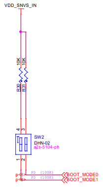
| − | * | + | * 原理图及启动模式选择<br> |
| − | <span style="background:#CCCCCC">schematic and | + | <span style="background:#CCCCCC">schematic and boot mode option</span><br> |
| − | [[文件: | + | [[文件:myimx6_mb140_2.8.0.1.png]] |
| − | + | <br> | |
| + | == '''RESET''' == | ||
{| class="wikitable" | {| class="wikitable" | ||
|- | |- | ||
| − | ! | + | !标号<br>(no.) |
| − | + | !接口<br>(interface) | |
| − | ! | + | !功能<br>(function) |
| + | !接口形式<br>(interface form) | ||
| + | !丝印<br>(silk screen) | ||
|- | |- | ||
| − | | | + | |10 |
| − | | | + | |RESET |
| − | |2 | + | |复位按钮<br>(reset button) |
| − | | | + | |按键(两脚)<br>(key(2 pins)) |
| − | + | |SW3 | |
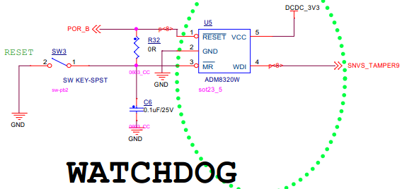
| − | | | + | |} |
| − | + | * 原理图<br> | |
| − | + | <span style="background:#CCCCCC">schematic</span><br> | |
| − | + | [[文件:myimx6_mb140_2.9.0.1.png]] | |
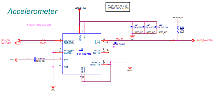
| + | == '''FXLS8471Q''' == | ||
| + | 说明:FXLS8471Q默认是不焊接的(即不属于MY-IMX6-MB140的标配)。<br> | ||
| + | <span style="background:#CCCCCC">Instruction:FXLS8471Q is not soldered by default.(It does not belong to the standard configuration of MY-IMX6-MB140)</span><br> | ||
| + | {| class="wikitable" | ||
|- | |- | ||
| − | + | !标号<br>(no.) | |
| − | + | !接口<br>(interface) | |
| − | + | !功能<br>(function) | |
| − | + | !接口形式<br>(interface form) | |
| − | + | !丝印<br>(silk screen) | |
| − | |||
| − | |||
| − | |||
| − | |||
| − | |||
|- | |- | ||
| − | | | + | |11 |
| − | | | + | |FXLS8471Q |
| − | | | + | |加速度传感器<br>(acceleration sensor) |
| − | | | + | |无 |
| + | |U8 | ||
| + | |} | ||
| − | + | * 原理图<br> | |
| − | + | <span style="background:#CCCCCC">schematic</span><br> | |
| − | + | [[文件:myimx6_mb140_2.10.0.1.png]] | |
| − | |||
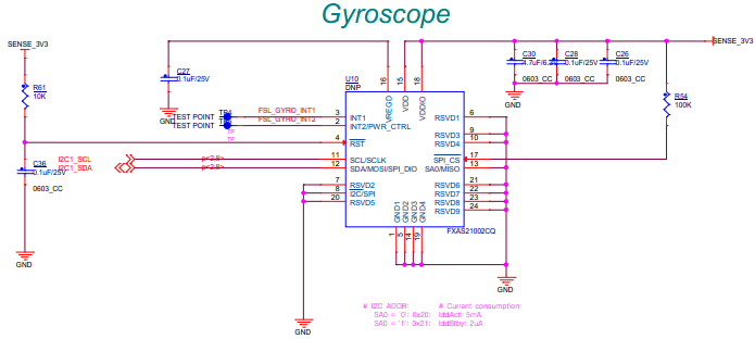
| + | == '''FXAS21002CQ''' == | ||
| + | 说明:FXAS21002CQ默认是不焊接的(即不属于MY-IMX6-MB140的标配)。<br> | ||
| + | <span style="background:#CCCCCC">Instruction:FXAS21002CQ is not soldered by default.(It does not belong to the standard configuration of MY-IMX6-MB140)</span><br> | ||
| + | {| class="wikitable" | ||
|- | |- | ||
| − | + | !标号<br>(no.) | |
| − | + | !接口<br>(interface) | |
| − | + | !功能<br>(function) | |
| − | + | !接口形式<br>(interface form) | |
| − | + | !丝印<br>(silk screen) | |
| − | |||
| − | |||
| − | |||
| − | |||
| − | |||
|- | |- | ||
| − | | | + | |12 |
| − | | | + | |FXAS21002CQ |
| − | | | + | |3轴数字陀螺仪<br>(3D digital gyroscope) |
| − | | | + | |无 |
| + | |U10 | ||
| + | |} | ||
| − | + | * 原理图<br> | |
| − | + | <span style="background:#CCCCCC">schematic</span><br> | |
| − | + | [[文件:myimx6_mb140_2.11.0.1.png]] | |
| − | |||
| + | == '''MAG3110''' == | ||
| + | 说明:MAG3110默认是不焊接的(即不属于MY-IMX6-MB140的标配)。<br> | ||
| + | <span style="background:#CCCCCC">Instruction:MAG3110 is not soldered by default.(It does not belong to the standard configuration of MY-IMX6-MB140)</span><br> | ||
| + | <span style="background:#CCCCCC"></span><br> | ||
| + | {| class="wikitable" | ||
|- | |- | ||
| − | + | !标号<br>(no.) | |
| − | + | !接口<br>(interface) | |
| − | + | !功能<br>(function) | |
| − | + | !接口形式<br>(interface form) | |
| − | + | !丝印<br>(silk screen) | |
| − | |||
| − | |||
| − | |||
| − | |||
| − | |||
|- | |- | ||
| − | |13 | + | |13 |
| − | | | + | |MAG3110 |
| − | | | + | |3轴地磁传感器<br>(3D magnetic sensor) |
| − | | | + | |无 |
| + | |U9 | ||
| + | |} | ||
| − | + | * 原理图<br> | |
| − | + | <span style="background:#CCCCCC">schematic</span><br> | |
| − | + | [[文件:myimx6_mb140_2.12.0.1.png]] | |
| − | |||
| + | == '''TS''' == | ||
| + | {| class="wikitable" | ||
|- | |- | ||
| − | + | !标号<br>(no.) | |
| − | + | !接口<br>(interface) | |
| − | + | !功能<br>(function) | |
| − | + | !接口形式<br>(interface form) | |
| − | + | !丝印<br>(silk screen) | |
| − | |||
| − | |||
| − | |||
| − | |||
| − | |||
|- | |- | ||
| − | | | + | |14 |
| − | | | + | |TS |
| − | | | + | |电阻触摸屏接口<br>(resistance touch screen inferface) |
| − | | | + | |PFC插座(抽屉式,4 Pin)<br>(PFC socket(drawer type,4 pins) |
| − | + | |J5 | |
| − | + | |} | |
| − | |||
| − | | | ||
| − | | | ||
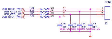
| + | * 原理图<br> | ||
| + | <span style="background:#CCCCCC">schematic</span><br> | ||
| + | [[文件:myimx6_mb140_2.13.0.1.png]] | ||
| + | {| class="wikitable" | ||
|- | |- | ||
| − | + | !接口序号<br>(interface order number) | |
| − | + | !引脚功能<br>(pin function) | |
| − | + | !使用的信号<br>(signal used) | |
| − | | | + | |rowspan=3| |
| − | + | !接口序号<br>(interface order number) | |
| − | | | + | !引脚功能<br>(pin function) |
| − | + | !使用的信号<br>(signal used) | |
| − | |||
| − | |||
| − | |||
|- | |- | ||
| − | | | + | |1 |
| − | | | + | |X- |
| − | | | + | |USB_OTG1_PWR |
| − | + | ||
| − | + | |3 | |
| − | | | + | |X+ |
| − | | | + | |USB_OTG2_OC |
| − | | | ||
| − | |||
| − | |||
|- | |- | ||
| − | | | + | |2 |
| − | | | + | |Y- |
| − | | | + | |USB_OTG1_OC |
| − | + | ||
| − | + | |4 | |
| − | | | + | |Y+ |
| − | | | + | |USB_OTG2_PWR |
| − | | | + | |} |
| − | | | ||
| + | == '''J6''' == | ||
| + | {| class="wikitable" | ||
|- | |- | ||
| − | + | !标号<br>(no.) | |
| − | + | !接口<br>(interface) | |
| − | + | !功能<br>(function) | |
| − | + | !接口形式<br>(interface form) | |
| − | + | !丝印<br>(silk screen) | |
| − | |||
| − | |||
| − | |||
| − | |||
| − | |||
|- | |- | ||
| − | | | + | |15 |
| − | | | + | |J6 |
| − | | | + | |功能插座<br>(function socket) |
| − | | | + | |双排插座(40 Pin)<br>(dual row socket(40 pins)) |
| + | |J3 | ||
| + | |} | ||
| − | + | * 原理图及使用的信号<br> | |
| − | + | <span style="background:#CCCCCC">schematic and signal used</span><br> | |
| − | + | [[文件:myimx6_mb140_2.14.0.1.png]] | |
| − | |||
| + | == '''J7''' == | ||
| + | {| class="wikitable" | ||
|- | |- | ||
| − | + | !标号<br>(no.) | |
| − | + | !接口<br>(interface) | |
| − | + | !功能<br>(function) | |
| − | + | !接口形式<br>(interface form) | |
| − | + | !丝印<br>(silk screen) | |
| − | |||
| − | |||
| − | |||
| − | |||
| − | |||
|- | |- | ||
| − | | | + | |16 |
| − | | | + | |J7 |
| − | | | + | |功能插座<br>(function socket) |
| − | | | + | |双排插座(40 Pin) |
| + | |SW1 | ||
| + | |} | ||
| − | + | * 原理图及使用的信号<br> | |
| − | + | <span style="background:#CCCCCC">schematic and signal used</span><br> | |
| − | + | [[文件:myimx6_mb140_2.15.0.1.png]] | |
| − | |||
| − | |||
| − | |||
| − | |||
| − | |||
| − | |||
| − | |||
| − | |||
| − | |||
| − | |||
| − | |||
| − | |||
| − | |||
| − | |||
| − | |||
| − | |||
| − | |||
| − | |||
| − | |||
| − | |||
| − | |||
| − | |||
| − | |||
| − | |||
| − | |||
| − | |||
| − | |||
| − | |||
| − | |||
| − | |||
| − | |||
| − | |||
| − | |||
| − | |||
| − | |||
| − | |||
| − | |||
| − | |||
| − | |||
| − | |||
| − | |||
| − | |||
| − | |||
| − | |||
| − | |||
| − | |||
| − | |||
== '''USER LIGHT''' == | == '''USER LIGHT''' == | ||
| 第654行: | 第786行: | ||
!丝印<br>(silk screen) | !丝印<br>(silk screen) | ||
|- | |- | ||
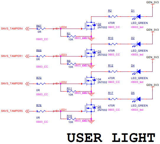
| − | | | + | |17 |
|USER LIGHT | |USER LIGHT | ||
|用户LED灯 | |用户LED灯 | ||
|LED灯(4个) | |LED灯(4个) | ||
| − | | | + | |D* |
|} | |} | ||
* 原理图及信号<br> | * 原理图及信号<br> | ||
<span style="background:#CCCCCC">schematic and signal</span><br> | <span style="background:#CCCCCC">schematic and signal</span><br> | ||
| − | [[文件: | + | [[文件:myimx6_mb140_2.16.0.1.png]] |
{| class="wikitable" | {| class="wikitable" | ||
|- | |- | ||
| + | !接口序号<br>(interface order number) | ||
| + | !引脚功能<br>(pin function) | ||
| + | !使用的信号<br>(signal used) | ||
| + | |rowspan=3| | ||
!接口序号<br>(interface order number) | !接口序号<br>(interface order number) | ||
!引脚功能<br>(pin function) | !引脚功能<br>(pin function) | ||
| 第673行: | 第809行: | ||
|D1 | |D1 | ||
|LED | |LED | ||
| − | | | + | |SNVS_TAMPER4 |
| + | |||
| + | |D4 | ||
| + | |LED | ||
| + | |SNVS_TAMPER8 | ||
|- | |- | ||
|D2 | |D2 | ||
|LED | |LED | ||
| − | | | + | |SNVS_TAMPER1 |
| − | + | ||
| − | | | + | |D5 |
|LED | |LED | ||
| − | | | + | |SNVS_TAMPER5 |
| − | |||
| − | |||
| − | |||
| − | |||
| − | |||
|} | |} | ||
| 第698行: | 第833行: | ||
!丝印<br>(silk screen) | !丝印<br>(silk screen) | ||
|- | |- | ||
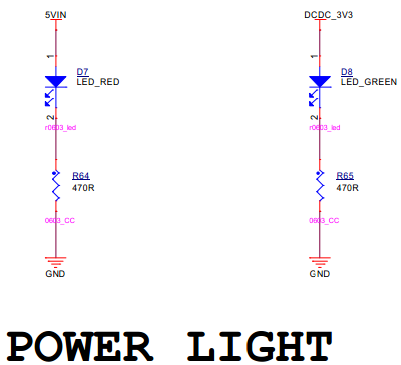
| − | | | + | |18 |
|POWER LIGHT | |POWER LIGHT | ||
|电源指示灯<br>(power indicator light) | |电源指示灯<br>(power indicator light) | ||
|LED灯(2个)<br>(LED light(2 units)) | |LED灯(2个)<br>(LED light(2 units)) | ||
| − | | | + | |D* |
|} | |} | ||
* 原理图及信号<br> | * 原理图及信号<br> | ||
<span style="background:#CCCCCC">schematic and signal</span><br> | <span style="background:#CCCCCC">schematic and signal</span><br> | ||
| − | [[文件: | + | [[文件:myimx6_mb140_2.17.0.1.png]] |
{| class="wikitable" | {| class="wikitable" | ||
|- | |- | ||
!丝印<br>(silk screen) | !丝印<br>(silk screen) | ||
!功能<br>(function) | !功能<br>(function) | ||
| + | |rowspan=2| | ||
| + | !丝印<br>(silk screen) | ||
| + | !功能<br>(function) | ||
|- | |- | ||
| − | + | |D7 | |
|红色LED电源指示灯<br>(red LED power indicator light) | |红色LED电源指示灯<br>(red LED power indicator light) | ||
| − | + | ||
|D8 | |D8 | ||
|绿色LED电源指示灯<br>(green LED power indicator light) | |绿色LED电源指示灯<br>(green LED power indicator light) | ||
|} | |} | ||
2018年4月25日 (三) 11:03的版本
目录
- 1 = 接口概览(interface overview) =
- 2 正面图(top view)
- 3 背面图(bottom view)
- 4 图示模块(graphic module)
- 5 = 接口功能(interface function) =
- 6 USB OTG
- 7 ENET
- 8 5V_IN
- 9 DEBUG UART
- 10 BOOT Device
- 11 TF
- 12 LCD DISPLAY()
- 13 BOOT MODE
- 14 RESET
- 15 FXLS8471Q
- 16 FXAS21002CQ
- 17 MAG3110
- 18 TS
- 19 J6
- 20 J7
- 21 USER LIGHT
- 22 POWER LIGHT
