“MYZR-IMX6-MB200 硬件介绍”的版本间的差异
| 第1行: | 第1行: | ||
| + | <div> | ||
= '''接口概览(overview of interfaces)''' = | = '''接口概览(overview of interfaces)''' = | ||
| 第487行: | 第488行: | ||
== '''RTC_Batter''' == | == '''RTC_Batter''' == | ||
丝印(silkscreen):BT1<br> | 丝印(silkscreen):BT1<br> | ||
| + | </div> | ||
2018年6月11日 (一) 15:39的版本
目录
- 1 接口概览(overview of interfaces)
- 2 接口功能(interface function)
- 2.1 18/24bit LVDS0
- 2.2 18/24bit RGB
- 2.3 18/24bit LVDS1
- 2.4 10M/100M Ethernet-1
- 2.5 耳机输出(earphone output)
- 2.6 麦克风输入(microphone input)
- 2.7 HDMI
- 2.8 SATA电源(SATA power supply)
- 2.9 OTG
- 2.10 SATA II
- 2.11 10M/100M Ethernet-2
- 2.12 USB扩展(USB expansion)
- 2.13 调试串口(debug uart)
- 2.14 主电源开关(main power supply switch)
- 2.15 主电源输入(main power supply switch)
- 2.16 复位(reset)
- 2.17 唤醒(wake up)
- 2.18 音量加(volume up)
- 2.19 音量减(volume down)
- 2.20 RS-232串口(RS-232 serial port)
- 2.21 RS-485串口(RS-485 serial port)
- 2.22 MINI-PCIE
- 2.23 串口扩展/TTL电平(serial port expansion/TTL electrical level)
- 2.24 GPIO/SD2
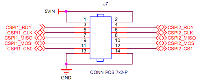
- 2.25 SPI扩展(SPI expansion)
- 2.26 SIM卡座(SIM cassette)
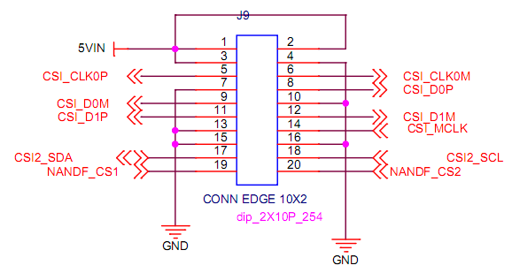
- 2.27 MIPI-CSI
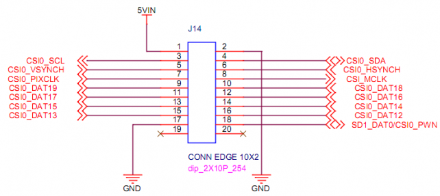
- 2.28 CMOS-CSI
- 2.29 CAN2
- 2.30 CAN1
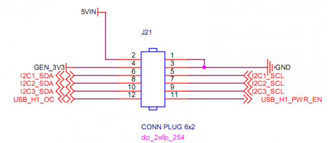
- 2.31 I2C扩展(I2C expansion)
- 2.32 GPS天线座(GPS antenna pedestal)
- 2.33 GPS
- 2.34 MINI_PCIE_FPC
- 2.35 SD3
- 2.36 WIFI
- 2.37 RTC
- 2.38 RTC_Batter
接口概览(overview of interfaces)
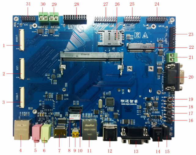
正面图(front view)
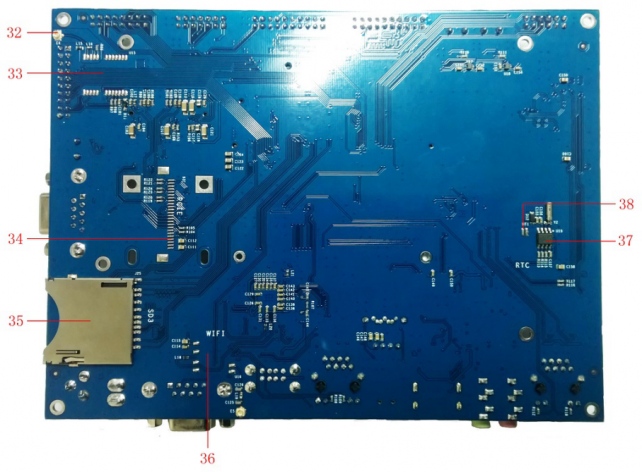
背面图(rear view)
图示模块(icon module)
| 图示 (graphic) |
接口描述 (interface description) |
丝印 (silk screen) |
图示 (graphic) |
接口描述 (interface description) |
丝印 (silk screen) |
|---|---|---|---|---|---|
| 1 | 18/24bit LVDS0 | J24 | 20 | UART4_RS232 | P1 |
| 2 | 18/24bit RGB | J23 | 21 | UART3_RS485 | J2 |
| 3 | 18/24bit LVDS1 | J22 | 22 | MINI_PCIE | J6 |
| 4 | 10M/100M Ethernet-1 | P4 | 23 | UART2/3/4/5_TTL | J1 |
| 5 | EAR | J20 | 24 | GPIO/SD2 | J4 |
| 6 | MIC | J18 | 25 | SPI1/2 | J7 |
| 7 | HDMI | J15 | 26 | SIM_CARD | CON1 |
| 8 | PWR_SATA | J12 | 27 | MIPI-CSI | J9 |
| 9 | MINIUSB | J13 | 28 | CMOS_CSI | J14 |
| 10 | SATA | J11 | 29 | CAN2 | J16 |
| 11 | 10M/100M Ethernet-2 | P3 | 30 | CAN1 | J19 |
| 12 | USBHOST | J8 | 31 | I2C1/2/3 | J21 |
| 13 | UART1_RS232 | P2 | 32 | GPS_ANT | E4 |
| 14 | PWR_Switch | J5 | 33 | GPS | U15 |
| 15 | DC_5V_IN | J3 | 34 | MINI_PCI_FPC | J26 |
| 16 | nRESET | SW1 | 35 | SD3 | J25 |
| 17 | KEY1 | SW2 | 36 | WIFI | U16 |
| 18 | KEY2 | SW3 | 37 | RTC | U19 |
| 19 | KEY3 | SW4 | 38 | RTC_Batter | BT1 |
接口功能(interface function)
18/24bit LVDS0
丝印(silk screen):J24
LVDS0液晶是24bit模式,兼容18bit模式,通过此接口可连接明远智睿公司生产的不同尺寸规格的电阻LVDS液晶屏和电容LVDS液晶屏。LVDS0接口座采用了进口连接器,抛弃了国内便宜的抽屉式,采用的是对面按压式,保证安装更容易,性能,连接性更好。
LVDS0 crystal liquid is 24 bit mode,compatible with 18bit mode,through which LVDS resistance screen panel and LVDS capacitor screen panel in different sizes and specifications produced by MYZR can be cnnected。LVDS0 interface block is build with connector imported,abandon the cheap drawer type produced domestically,which is opposite press type to ensure easier installation,better performance and connectivity 。
引脚及信号定义如下:
definition of pin & signal as below:

| 引脚 (pin) |
信号 (singnal) |
描述 (description) |
|---|---|---|
| J24-16 | SD1_DAT1/TOUCH_nEINT1 | GPIO控制 (GPIO control) |
| J24-17 | NANDF_CS3 | GPIO控制 (GPIO control) |
| J24-19 | DISP0_CONTRAST | LVDS0背光调节 (LVDS0 backlight adjustment) |
| J24-21 | TOUCH_SCL | I2C时钟 (I2C clock) |
| J24-22 | TOUCH_SDA | I2C数据 (I2C data) |
18/24bit RGB
丝印(silkscreen):J23
RGB液晶是24bit模式,兼容18bit/16bit模式,通过此接口可连接明远智睿公司生产的不同尺寸规格的电阻RGB液晶屏和电容RGB液晶屏。RGB液晶接口座采用了进口连接器,抛弃了国内便宜的抽屉式,采用的是对面按压式,保证安装更容易,性能,连接性更好。
RGB crystal liquid is 24bit mode,compatible to 18bit/16bit mode,through which RGB resistance screen panel and RGB capacitor screen panel in different sizes and specifications produced by MYZR can be cnnected,RGB interface block is build with connector imported,abandon the cheap drawer type produced domestically,which is opposite press type to ensure easier installation,better performance and connectivity。
引脚及信号定义:
definition of pin & signal:

| 引脚 (pin) |
信号 (signal) |
描述 (description) |
|---|---|---|
| J23-31 | SD1_DAT1/TOUCH_nEINT1 | GPIO控制 (GPIO control) |
| J23-30 | NANDF_CS3 | GPIO控制 (GPIO control) |
| J23-19 | DISP0_CONTRAST | LVDS0背光调节 (LVDS0 backlight adjustment) |
| J23-32 | TOUCH_SCL | I2C时钟 (I2C clock) |
| J23-33 | TOUCH_SDA | I2C数据 (I2C data) |
18/24bit LVDS1
丝印(silk screen):J22
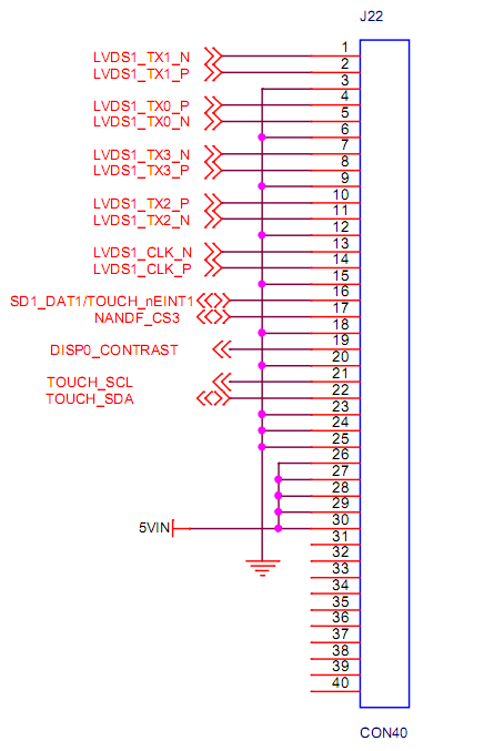
LVDS1液晶接口跟LVDS0液晶接口定义,接插件型号完全一样,用户可以直接把LVDS0处的液晶直接接到LVDS1处。
LVDS1 crystal liquid interface is the same as LVDS0 in terms of definition and connector model,users can connect crytal liquid in LVDS0 directly to LVDS1。
引脚及信号定义:
definition of pin & signal:
| 引脚 (pin) |
信号 (signal) |
描述 (description) |
|---|---|---|
| J22-16 | SD1_DAT1/TOUCH_nEINT1 | GPIO控制 (GPIO control) |
| J22-17 | NANDF_CS3 | GPIO控制 (GPIO control) |
| J22-19 | DISP0_CONTRAST | LVDS0背光调节 (LVDS0 backlight adjustment) |
| J22-21 | TOUCH_SCL | I2C时钟 (I2C clock) |
| J22-22 | TOUCH_SDA | I2C数据 (I2C data) |
10M/100M Ethernet-1
丝印(silk screen):P4
接口属性:百兆网标准接口
interface property:100 - Mbps Ethernet standard interface
耳机输出(earphone output)
丝印(silk screen):J20
接口属性:音频信号输出,3.5mm接口
interface property:audio signal output,3.5mm interface
麦克风输入(microphone input)
丝印(silk screen):J18
接口属性:音频信号输入,3.5mm接口
interface propoerty:audio signal input,3.5mm interface
HDMI
丝印(silkscreen):J5
接口属性:HDMI-1.4标准接口
interface property:HDMI-1.4 standard interface
SATA电源(SATA power supply)
丝印(silkscreen):J12
引脚及信号定义:
definition of pin & signal:
| 引脚 (pin) |
信号 (signal) |
描述 (description) |
|---|---|---|
| J12-1 | 5VIN | 5V电源输入 (5V power input) |
| J12-2 | GND | 数字地 (digital) |
| J12-3 | GND | 数字地 (digital) |
| J12-4 | NC | 未连接 (unconnected) |
OTG
丝印(silkscreen):J5
接口属性:USB ON-The-GO,用于烧写
interface property:USB ON-The-GO,for burn and write
SATA II
丝印(silkscreen):J11
接口属性:3Gbps SATA II标准接口
interface property:3Gbps SATA II standard interface
10M/100M Ethernet-2
丝印(silkscreen):P3
接口属性:百兆网标准接口
interface property:100 - Mbps Ethernet standard interface
USB扩展(USB expansion)
丝印(silkscreen):J8
接口属性:USB1扩展双USB,标准USB接口
interface property:USB1 expanded to dual USB,standard USB interface
调试串口(debug uart)
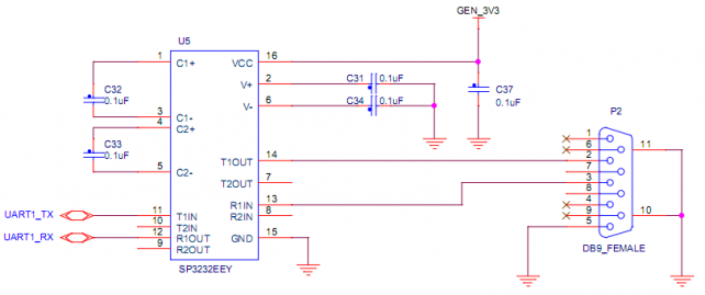
丝印(silkscreen):P2
接口属性:3线标准RS232接口,用作调试串口
interface property:3 thread standard RS232 port,for debug of sirial port
主电源开关(main power supply switch)
丝印(silkscreen):J3
接口属性:电源开关
interface property:power supply switch
状态属性:—,闭合;O,断开
status property:—,close;O,off
主电源输入(main power supply switch)
丝印(silkscreen):J4
接口属性(interface property):
内正外负插孔
jack with inside positive and outside negative
     电压(voltage):5V

     电流(current):2.5A及以上
复位(reset)
丝印(silkscreen):SW1
功能:复位
function:reset
唤醒(wake up)
丝印(silkscreen):SW2
接口属性:休眠唤醒
interface property:sleeping wake up
音量加(volume up)
丝印(silkscreen):SW3
接口属性:音量控制(音量加)
interface property:volume control(volume up)
音量减(volume down)
丝印(silkscreen):SW2
接口属性:音量控制(音量减)
interface property:volume control(volume down)
RS-232串口(RS-232 serial port)
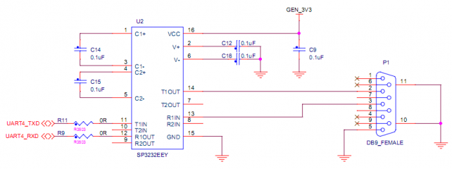
丝印(silkscreen):P1
接口属性:UART4,3线标准RS232接口
interface property:UART4,3 thread standard RS232 port
RS-485串口(RS-485 serial port)
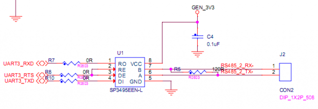
丝印(silkscreen):J2
接口属性:UART3,RS-485串口
interface property:UART3,RS-485 serial port
MINI-PCIE
丝印(silkscreen):J6
接口属性:标准MINI-PCIE接口
interface property:standard MINI-PCIE port
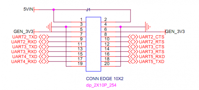
串口扩展/TTL电平(serial port expansion/TTL electrical level)
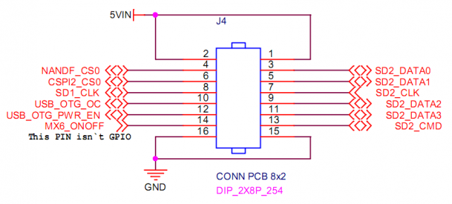
GPIO/SD2
SPI扩展(SPI expansion)
SIM卡座(SIM cassette)
丝印(silkscreen):CON1
接口属性:标准的SIM卡座
interface property:standard SIM cassette
MIPI-CSI
CMOS-CSI
CAN2
丝印(silkscreen):J16
接口属性:CAN2
interface property:CAN2

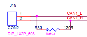
CAN1
丝印(silkscreen):J19
接口属性:CAN1
interface property:CAN1
I2C扩展(I2C expansion)
GPS天线座(GPS antenna pedestal)
丝印(silkscreen):E4
接口属性:天线座
interface property:antenna pedestal
GPS
丝印(silkscreen):U15
模块型号:NEO-6M
module model:NEO-6M
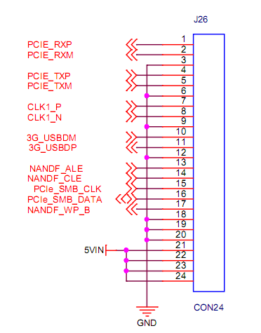
MINI_PCIE_FPC
丝印(silkscreen):J26
注意:跟标准的MINI_PCIE座子不能同时使用,即2选1。
note:can't be used with MINI_PCIE simultaneously,e.g can only choose one from the two。
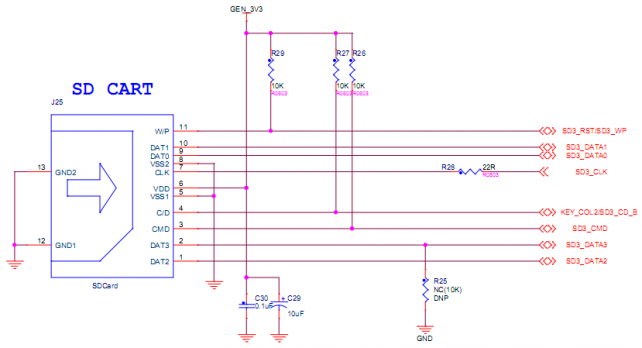
SD3
丝印(silkscreen):J25
接口属性:标准SD卡座
interface property:standard SD cassette
WIFI
丝印(silkscreen):U16
模块型号:UM12BS
module model:UM12BS

RTC
丝印(silkscreen):U19
接口属性:I2C通信的实时时钟
interface property:real clock for I2C communication
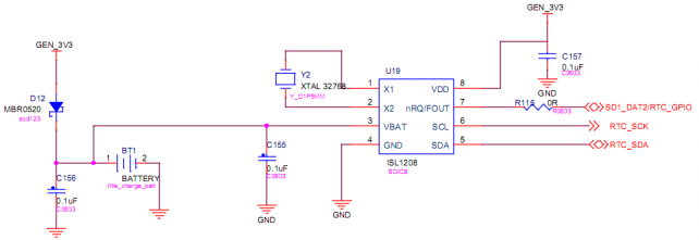
RTC_Batter
丝印(silkscreen):BT1
