“MYZR-IMX6-EK336 Quick Start”的版本间的差异
(创建页面,内容为“<div> = '''Prepare development board kits''' = ---- Development board kits consist of development board and its accessories.<br> =='''Development board accessory''...”) |
(→Development Board Interface Overview) |
||
| 第24行: | 第24行: | ||
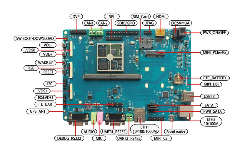
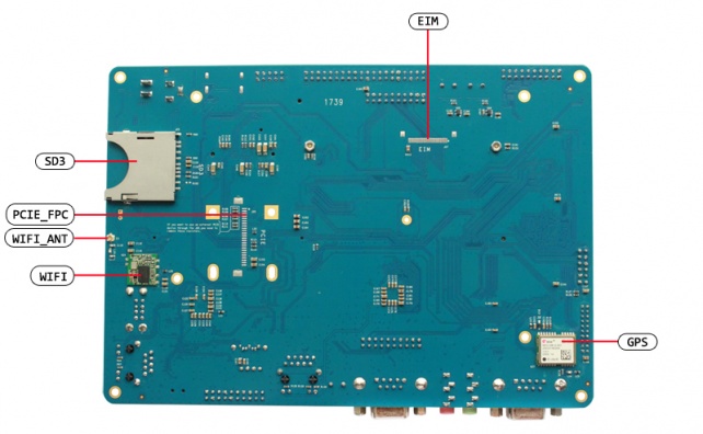
:Before we start the development board we need to know some interfaces and connect these interfaces correctly to the computer. Here I first understand the MY-IMX6-MB336 interface.<br> | :Before we start the development board we need to know some interfaces and connect these interfaces correctly to the computer. Here I first understand the MY-IMX6-MB336 interface.<br> | ||
== MY-IMX6-(MB314 + CB336) front view == | == MY-IMX6-(MB314 + CB336) front view == | ||
| − | [[File:MY-IMX6-EK336-front.jpg| | + | [[File:MY-IMX6-EK336-front.jpg|850px]]<br> |
== MY-IMX6-(MB314 + CB336) rear view == | == MY-IMX6-(MB314 + CB336) rear view == | ||
| − | [[File:MY-IMX6-EK336-back.jpg|642px]]<br> | + | [[File:MY-IMX6-EK336-back.jpg|642px]]<br> |
='''Fast boot development board'''= | ='''Fast boot development board'''= | ||
2020年4月16日 (四) 09:25的版本
目录
Prepare development board kits
Development board kits consist of development board and its accessories.
Development board accessory
Development board consist of following components:
- MY-IMX6-CB336(core board)one unit
- MY-IMX6-MB314(base board)one unit
- Circuit board of screen panel one unit
- Crystal liquid screen,one piece
- Touch screen,one unit
- MY-IMX6-CB336(core board)one unit
Development board accessory
Development board accessories include:
- Power Adapter ,one piece
- USB download line ,one piece
- Network cable ,one piece
- Serial cable ,one piece
- Power Adapter ,one piece
Development Board Interface Overview
- Before we start the development board we need to know some interfaces and connect these interfaces correctly to the computer. Here I first understand the MY-IMX6-MB336 interface.
MY-IMX6-(MB314 + CB336) front view
MY-IMX6-(MB314 + CB336) rear view
Fast boot development board
1)Skip to segment “switch off power supply”,“power supply connection cable”in chapter of "connection between development and computer" for operation.
2)Skip to segment "power up for development board" in chapter "development board boot",continue the operations with this step.
- Instruction:In mode of fast boot,there is not connection between development board and computer,but system booting status can be viewed on the screen.
Connection between development board and computer
Since we need to connect development board with computer in many cases,below is the instructions about the job.
Close Power Supply switch
- We need to check switching status of development board power supply before the connection between development board and computer,to ensure power supply switch in off status.
- Ways to make power supply switch in off status:press development board power supply switch(icon ”PWR_SWITCH” on front view of development board) to be "off" status(—:closed,O:off)
Connection of serial lines
Cable connection
- Connect one end of serial line to debug serial port of development board(icon ”RS232_UART1” on front view of development board),another connect to computer.
- If there is not serial pots in the computer,need to prepare by yourself USB to serial line and connect.
- If there is no connection of serial line with computer, interaction can't be done with development board via serial port, but no affection on development board booting and burning system.
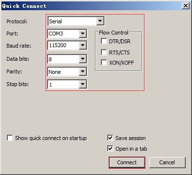
Serial port terminal tool configuration
- To find terminal number we are using through Windows device manager in computer.
- Configure every parameter for serial port terminal tool.
Connection of internet line
Connect one end of network cable with RGMII of development board(icon ”ETH1” on front view),another end inserted into LAN port of computer.
Connection of USB download line
Connect one end of USB line with OTG of development board (icon ”USBOTG” on front view),another end inserted into USB port of computer.
Connection of power supply cable
Connect one end of power supply cable with 5V power input of development board(icon ”DC_IN” on front view),another end connected with power supply socket.
Booting of development board
After all the operations in "connection between development board and computer"were completed in order,the connection of devlopment board with computer is ready。to boot the board, we need to power on the development board.
Power on development board
Press development board power supply switch (icon “PWR_SWITCH”on front view)to closed status(—:closed,O:off)
Observe booting condition
U-boot dynamics
You will see the LCD screen lit up and display Freescale and MYZR’s LOGO.
Serial port terminal dynamics
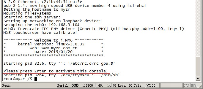
You can see the information about booting process outputed during the course of development board booting through serial port terminal.
Kernel booting dynamics
After the kernel boots at a certain stage, you can see the penguins on the LCD screen.
System dynamics
1)Linux system
- After the system booting is completed, the little penguin will be still displayed on the LCD screen.
- The serial port output message prompts the user to press " Enter " , and then press " Enter " on the computer to enter the system .
2)Linux QT system
- After the system booting is completed, the development board will run a QT sample program, and you can see the QT sample program running on the LCD screen.
3)Ubuntu system
- After the system is up, you can see the Ubuntu system interface on the LCD screen.


