“MYZR-RK3288-EK314 Quick Start”的版本间的差异
(创建页面,内容为“<div> = '''Prepare development board kits''' = ---- Development board kits consist of development board and its accessories.<br> == '''Development board''' == Devel...”) |
(→Overview of development board interface) |
||
| 第34行: | 第34行: | ||
MY-R3288-MB314 Front view:<br> | MY-R3288-MB314 Front view:<br> | ||
| − | [[File:myrk3288_mb314_1.1.0.1.jpg| | + | [[File:myrk3288_mb314_1.1.0.1.jpg|1000px]]<br> |
MY-R3288-MB314 Rrear view:<br> | MY-R3288-MB314 Rrear view:<br> | ||
| − | [[File:myrk3288_mb314_1.2.0.1.jpg| | + | [[File:myrk3288_mb314_1.2.0.1.jpg|1000px]]<br> |
= '''Fast boot development board''' = | = '''Fast boot development board''' = | ||
2020年4月16日 (四) 10:06的版本
目录
- 1 Prepare development board kits
- 2 Overview of development board interface
- 3 Fast boot development board
Prepare development board kits
Development board kits consist of development board and its accessories.
Development board
Development board consist of following components:
- MY-RK3288-CB314 (core board),one unit
- MY-RK3288-MB314 (bottom board),one unit
- Circuit board of screen panel,one unit
- Crystal liquid screen,one piece
- Touch screen,one unit
Development board accessory
Development board accessories include:
- Adaptor,one unit
- USB download cable,one piece
- Internet cable,one piece
- Serial line,one piece
Overview of development board interface
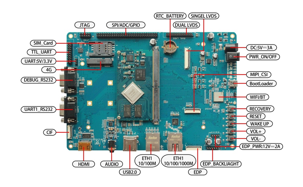
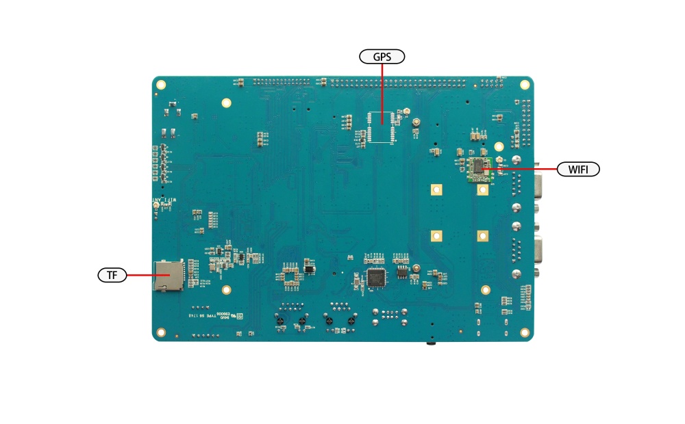
Before starting the development board, we need to recognize some interfaces and connect them to the computer correctly.Here I first know the interface of MY-RK3288-MB314 .
MY-R3288-MB314 Front view:

MY-R3288-MB314 Rrear view:

Fast boot development board
1)Skip to "off power switch" and "connect power line" in the section "connection between development board and computer".
2)Skip to "power the development board" in the section "start the development board" and proceed from there.
Note: the development board is not connected to the computer in the fast start mode, but the system start state can be seen from the LCD screen.
Development board is connected to the computer
Because in many cases we need to connect the development board to the computer, the following describes how the development board connects to the computer.
Power switch off
1) Before connecting the development board to the computer, we need to check the power switch status of the development board and ensure that the power switch is disconnected.
2) The way to keep the POWER switch on the development board in a disconnected state is to press the POWER switch on the development board (the MAIN POWER SW shown in the drawing on the front of the development board) to a disconnected state (-- : close, O: disconnect).
Connection of serial lines
Connect one end of the serial port line to the DEBUG UART interface on the front of the development board, and the other end to the computer.
Introductions:
1)If the computer does not have a serial port, you need to prepare your own USB cable and connect it.
2)If there is no connection to the serial port line, you will not be able to interact with the development board in a serial port manner.However, it does not affect the starting and burning system of the development board.
Serial port terminal tool configuration
1)Find the port number we use on the computer through the Windows device manager.
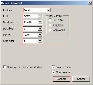
2)Configure the parameters of the serial port terminal tool.
- The SecureCRT & USB serial port 3 example configuration is as follows:
- The SecureCRT & USB serial port 3 example configuration is as follows:
Network connection
Connect one end of the wire to the 1000M or 10M/100M Ethernet interface on the front of the development board, and insert the other end of the wire into the computer's network port.
USB download the connection
Connect one end of the USB cable to the OTG interface on the front of the development board, and insert the other end into the USB interface of the computer.
Connect the power cord
Connect one end of the power cord to the DC_5V_IN interface on the front of the development board, and one end to the power socket.
Start the development board
1)After working in sequence in "development board to computer connection", our development board to computer connection has been completed.
2)To enable the development board to start up, we need to power the development board.
3)Press the MAIN POWER SW to the closed state (-- : close, O: disconnect) on the front of the development board POWER switch.
4)Then hold down the SLEEP WAKE button on the front of the development board until the LED light of the development board lights up.
Observe booting condition
Serial port terminal dynamics
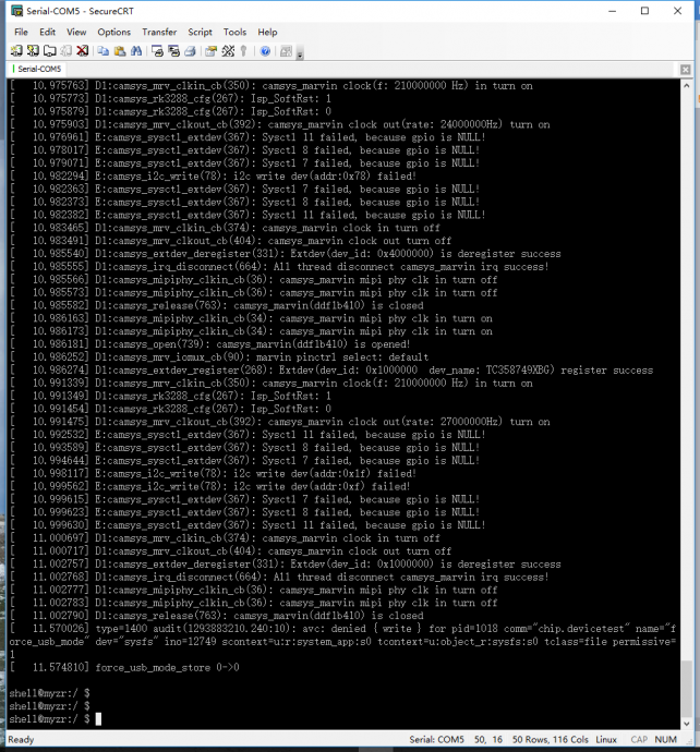
You can see the information about booting process outputed during the course of development board booting through serial port terminal.
- After starting, the serial port printing information is as follows:
Display status
If the LCD is properly connected, you will see an output image of the display during the startup of the development board.

