|
|
| (未显示同一用户的8个中间版本) |
| 第1行: |
第1行: |
| − | = '''1 适用范围(applicable scope)''' =
| + | [^_^]: MY-IMX Android-5.1.1 测试手册 |
| | | | |
| − | [[文件:Android test 1.jpg|640px]]<br>
| + | ## **适用范围** |
| | + | {| class="wikitable" |
| | + | |- |
| | + | !colspan=2 style="background:yellow;color:blue"| 适用范围 |
| | | | |
| − | = '''测试项目(test project)''' =
| + | |- |
| − | == '''UART测试(UART test)''' == | + | !style="background:blue;color:white"| 评估板型号 |
| − | === '''测试说明(test instruction)''' === | + | !style="background:blue;color:white"| 系统类型 |
| | | | |
| | + | |- |
| | + | | MYZR-IMX6-EK200 |
| | + | | Android 5.1.1 |
| | | | |
| − | (1)总共有4个串口,测试程序默认选择Uart2,可以根据需要选择其他串口。<br>
| + | |- |
| − | <span style="background:#CCCCCC">total 4 serial interfaces,defaulted Uart2 by test program,but you can choose other interface as per what is needed。</span><br>
| + | | MYZR-IMX6-EK314 |
| − | (2)测试之前需要短接串口的收发管脚,不同的开发板短接的管脚有所不同,对应关系如下图:<br>
| + | | Android 5.1.1 |
| − | <span style="background:#CCCCCC">need to shorten send&receive pins of interface before test,pins shortened are different among different development boards,correspondence as below :</span><br>
| |
| − | [[文件:Android test 2.1.1.jpg|640px]]<br>
| |
| | | | |
| − | (3)这里选择默认配置,即Uart2,短接其对应的管脚。<br>
| + | |- |
| − | <span style="background:#CCCCCC">here choose defaulted configuration,i.e Uart2,shorten the according pins。</span><br>
| + | |} |
| − | === '''测试方法(test method)''' ===
| |
| | | | |
| | | | |
| − | (1)点击“Uart”按钮,启动测试程序。<br>
| + | ## **测试项目** |
| − | <span style="background:#CCCCCC">click“Uart”button,to boot test program。</span><br>
| + | ###一.uart测试 |
| − | [[文件:Android test 2.1.2.jpg|640px]]<br>
| + | 测试之前需要短接串口的收发管脚,不同的开发板短接的管脚有所不同,对应关系如下图: |
| − | (2)点击“OpenDev”打开设备。<br>
| + | {| class="wikitable" |
| − | <span style="background:#CCCCCC">click“OpenDev”to open device。</span><br>
| + | |- |
| − | (3)点击“send”发送数据。<br>
| + | !style="background:blue;color:white"| 评估板型号 |
| − | <span style="background:#CCCCCC">click“send”to send data。</span><br>
| + | !style="background:blue;color:white"| UARTx |
| − | 如果成功收到数据,文本框会在右边显示出来,说明测试成功,如下图:<br>
| + | !style="background:blue;color:white"| Rx |
| − | <span style="background:#CCCCCC">if there is a successful receiving of data,texbox will be popuped on the right side,i.e.a success of test,as below:</span><br>
| + | !style="background:blue;color:white"| Tx |
| − | [[文件:Android test 2.1.2 2.jpg|640px]]<br>
| + | !style="background:blue;color:white"| 系统接口 |
| − | 如果没有收到数据,则测试失败,请检查Uart管脚是否短接,错误如下图:<br>
| |
| − | <span style="background:#CCCCCC">if not receiving of data,that means a failure of test, please check out whether pins were shortened, errors as below:</span><br>
| |
| − | [[文件:Android test 2.1.2 3.jpg|640px]]<br>
| |
| | | | |
| − | (5)测试完成,点击关闭,退出串口测试。<br>
| + | |- |
| − | <span style="background:#CCCCCC">when test is finished,click close,to exit the test of serial interface。</span><br>
| + | |rowspan=4|MYZR-IMX6-EK200 |
| | + | |UART2 |
| | + | |J1:9 |
| | + | |J1:7 |
| | + | |ttymxc1 |
| | | | |
| | + | |- |
| | + | |UART3 |
| | + | |J1:13 |
| | + | |J1:11 |
| | + | |ttymxc2 |
| | | | |
| | + | |- |
| | + | |UART4 |
| | + | |J1:17 |
| | + | |J1:15 |
| | + | |ttymxc3 |
| | | | |
| − | == '''SPI测试(SPI test)''' ==
| + | |- |
| − | === '''测试说明(test instruction)''' ===
| + | |UART5 |
| − | (1)测试之前需要短接SPI的管脚,不同的开发板短接的管脚有所不同,对应关系如下:<br>
| + | |J1:16 |
| − | <span style="background:#CCCCCC">need to shorten SPI pins before test,pins shortened are different among different development boards,correspondence as below:</span><br>
| + | |J1:18 |
| − | [[文件:Android test 2.2.1.jpg|640px]]<br>
| + | |ttymxc4 |
| | | | |
| − | (2)EK200与测试程序对应的是SPI2;EK314与测试程序对应的是SPI1;根据实际情况短接相应的管脚。<br>
| + | |- |
| − | <span style="background:#CCCCCC">EK200 match up with test program by SPI2;EK314 match up with test program by SPI1;so need to shorten pins according to actual condition。</span><br>
| + | |rowspan=4|MYZR-IMX6-EK314 |
| − | === '''2.2.2测试方法(2.2.2 test method)''' ===
| + | |UART2 |
| − | (1)点击“SPI”按钮,启动测试程序。<br>
| + | |J12:9 |
| − | <span style="background:#CCCCCC">click“SPI”button,to boot test program。</span><br>
| + | |J12:10 |
| − | [[文件:Android test 2.2.2.jpg|640px]]<br> | + | |ttymxc1 |
| | + | |
| | + | |- |
| | + | |UART3 |
| | + | |J12:12 |
| | + | |J12:13 |
| | + | |ttymxc8 |
| | + | |
| | + | |- |
| | + | |UART4 |
| | + | |J12:17 |
| | + | |J12:15 |
| | + | |ttymxc3 |
| | + | |
| | + | |- |
| | + | |UART5 |
| | + | |J12:16 |
| | + | |J12:18 |
| | + | |ttymxc4 |
| | + | |
| | + | |} |
| | + | |
| | + | |
| | + | [[文件:Android test 1.2.jpg|640px]] |
| | | | |
| − | (2)点击“OpenDev”打开设备。<br>
| + | *测试方法: |
| − | <span style="background:#CCCCCC">click“OpenDev”to open device。</span><br>
| + | 1)选择要测试的串口,设置好波特率 |
| − | (3)点击“send”发送数据。如果成功收到数据,文本框会在右边的显示出来,说明测试成功,如下图:<br>
| + | 2)点击打开设备按钮 |
| − | <span style="background:#CCCCCC">click“send”to send data。if there is a successful receiving of data,texbox will be popuped on the right side,i.e.a success of test,as below:</span><br>
| + | 3)输入要发送的内容 |
| − | [[文件:Android test 2.2.2 2.jpg|640px]]<br>
| + | 4)点击传送数据按钮 |
| − | 如果没有收到数据,则测试失败,请检查管脚是否短接,错误如下图:<br>
| + | 5)点击关闭设备按钮 |
| − | <span style="background:#CCCCCC">if not receiving of data,that means a failure of test, please check out whether pins were shortened, errors as below:</span><br>
| + | |
| − | [[文件:Android test 2.2.2 3.jpg|640px]]<br> | + | ###**二.Gpio测试** |
| | + | [[文件:Android test 1.3.jpg|640px]] |
| | | | |
| − | (4)测试完成,点击关闭,退出测试程序。<br>
| + | *测试方法: |
| − | <span style="background:#CCCCCC">when test is finished,click close,to exit the test program。</span><br>
| + | 1)输入:输入一个gpio设置为输入管脚 |
| − | == '''I2C测试(I2C test)''' ==
| + | 2)输出:输入一个gpio设置为输出管脚 |
| − | === '''测试说明(test instruction)''' === | + | 3)点击高/低电平按钮设置电平 |
| − | 评估板总共有3条IIC总线,每条总线都有设备,测试程序仅仅是列出每条总线的设备而已,其他不做测试。<br>
| + | 4)用万用表测试输出管脚的电平 |
| − | <span style="background:#CCCCCC">there are total 3 IIC bus on evaluation board,each bus has its own device,test program only list the device for each bus,not for test。</span><br>
| + | |
| − | === '''测试方法(test method)''' === | + | ###**三.Spi测试** |
| − | (1)点击“I2C”按钮,启动测试程序。<br>
| + | 测试之前需要短接 SPI 的管脚,不同的开发板短接的管脚有所不同,对应关系如下: |
| − | <span style="background:#CCCCCC">click“I2C”button,to boot test program。</span><br>
| + | {| class="wikitable" |
| − | [[文件:Android test 2.3.2.jpg|640px]]<br>
| + | |- |
| − |
| + | !style="background:blue;color:white"| 评估板型号 |
| − | (2)点击“ListI2C”,列出所有I2C总线,总共3条,如下图:<br>
| + | !style="background:blue;color:white"| SPIx |
| − | <span style="background:#CCCCCC">click“ListI2C”,to list all I2C bus,total 3 units,the following figure:</span><br>
| + | !style="background:blue;color:white"| MISO |
| − | [[文件:Android test 2.3.2 2.jpg|640px]]<br>
| + | !style="background:blue;color:white"| MOSI |
| | | | |
| − | (3)点击“ListDevice”列出其中一条总线上的所有设备,默认是i2c-0,如下图:<br>
| + | |- |
| − | <span style="background:#CCCCCC">click“ListDevice”to list all devices on one of the bus,default is i2c-0,as below:</span><br>
| + | |rowspan=2|MYZR-IMX6-EK200 |
| − | [[文件:Android test 2.2.2 3.jpg|640px]]<br>
| + | |SPI1 |
| | + | |J7:7 |
| | + | |J7:9 |
| | | | |
| − | (4)点击右边的下拉菜单,分别列出另外两条总线上的设备,如下图:<br>
| |
| − | <span style="background:#CCCCCC">click drop-down manu on right,to get separate list of devices on the other two bus,example:</span><br>
| |
| − | [[文件:Android test 2.2.2 4.jpg|640px]]<br>
| |
| − | [[文件:Android test 2.2.2 5.jpg|640px]]<br>
| |
| | | | |
| | + | |- |
| | + | |SPI2 |
| | + | |J7:8 |
| | + | |J7:10 |
| | | | |
| − | (5)测试完成,退出测试。<br>
| |
| − | <span style="background:#CCCCCC">finish test,exit test。</span><br>
| |
| − | == '''CAN测试(CAN test)''' ==
| |
| − | === '''测试说明(test instruciton)''' ===
| |
| − | 测试之前需要连接CAN的管脚,将CAN1的CAN_L和CAN2的CAN_L连接,将CAN1的CAN_H和CAN2的CAN_H连接。<br>
| |
| − | <span style="background:#CCCCCC">need to connect CAN pins before test,connect CAN_L of CAN1 with CAN_L of CAN2,connect CAN_H of CAN1 with CAN_H CAN2。</span><br>
| |
| − | === '''测试方法(test method)''' ===
| |
| − | (1)点击“CAN”按钮,启动测试程序<br>
| |
| − | <span style="background:#CCCCCC">click“CAN”button,to boot test program</span><br>
| |
| − | [[文件:Android test 2.4.2 .jpg|640px]]<br>
| |
| − | (2)点击“OpenDev”打开设备,点击“Send”,发送数据,如果成功接收到数据,文本框会在右边显示出来,如下图:)<br>
| |
| − | <span style="background:#CCCCCC">click“OpenDev”to open device,click“Send”to send data,if there is a successful receiving of data,texbox will be popuped on the right side,as below:</span><br>
| |
| − | [[文件:Android test 2.4.2 2.jpg|640px]]<br>
| |
| | | | |
| − | 如果没有收到数据,则测试失败,请检查CAN的管脚是否短接,错误如下图:<br>
| + | |- |
| − | <span style="background:#CCCCCC">if not receiving of data,that means a failure of test, please check out whether CAN pins were shortened,errors as below:</span><br>
| + | |rowspan=2|MYZR-IMX6-EK314 |
| − | [[文件:Android test 2.4.2 3.jpg|640px]]<br>
| + | |SPI1 |
| | + | |J13:7 |
| | + | |J13:11 |
| | | | |
| − | (3)测试完成,退出CAN测试。<br>
| + | |- |
| − | <span style="background:#CCCCCC">test is over,exit CAN test。</span><br>
| + | |SPI2 |
| − | == '''USB&SD测试(USB&SD test)''' ==
| + | |J13:6 |
| − | === '''测试说明(test instruction)''' ===
| + | |J13:12 |
| − | (1)检测USB和SD读写是否正常。<br>
| |
| − | <span style="background:#CCCCCC">check out whether USB and SD read & write is normal or not。</span><br>
| |
| − | === '''测试方法(test method)''' ===
| |
| − | (1)点击“SD/U盘”按钮,启动测试程序。<br>
| |
| − | <span style="background:#CCCCCC">click“SD/U disk”button,to boot test program。</span><br>
| |
| − | [[文件:Android test 2.4.5.jpg|640px]]<br>
| |
| − | (2)插入U盘或者SD卡,点击“SD”或“U盘”按钮读出SD卡或U盘的内容。<br>
| |
| − | <span style="background:#CCCCCC">insert U disk or SD card,click“SD”or“U disk”button to read out the content of SD card or U disk。</span><br>
| |
| − | [[文件:Android test 2.4.5 2.jpg|640px]]<br>
| |
| | | | |
| − | (3)测试完成,退出测试程序<br>
| + | |- |
| − | <span style="background:#CCCCCC">test is over,exit test program</span><br>
| + | |} |
| − | == '''WIFI&网口测试(WIFI& lan port test)''' ==
| + | |
| − | === '''测试说明(test instruction)''' ===
| + | *测试方法: |
| − | 检测WIFI与网口功能。<br>
| + | 1)点击打开设备按钮 |
| − | <span style="background:#CCCCCC">check out function of WIFI and lan port。</span><br>
| + | 2)输入要发送的内容 |
| − | === '''WIFI测试方法(WIFI test method)''' ===
| + | 3)点击传送数据按钮 |
| − | (1)点击“WIFI按钮”,启动测试程序。<br>
| + | 4)点击关闭设备按钮 |
| − | <span style="background:#CCCCCC">click“WIFI button”,to boot test program。</span><br>
| + | |
| − | [[文件:Android test 2.6.2.jpg|640px]]<br>
| + | ###**四.i2c测试** |
| − | (2)点击“wifi”开关,打开wifi后点击“search”搜索wifi.<br>
| + | [[文件:Android test 1.5.jpg|640px]] |
| − | <span style="background:#CCCCCC">click“wifi”switch,after open wifi then click“search”to search wifi.</span><br>
| |
| − | [[文件:Android test 2.6.2 2.jpg|640px]]<br> | |
| − | (3)点击要连接的Wifi,输入密码进行连接。<br>
| |
| − | <span style="background:#CCCCCC">click Wifi which will be linked,enter password for the link。</span><br>
| |
| − | (4)连接成功后点击“Link”按钮连接百度。<br>
| |
| − | <span style="background:#CCCCCC">if a successful link,then click“Link”to link with baidu。</span><br>
| |
| − | (5)若连接失败检查网络是否畅顺。<br>
| |
| − | <span style="background:#CCCCCC">if failure of link,please check out whether network is working。</span><br>
| |
| − | === '''网口测试方法(lan port test method)''' ===
| |
| − | (1)将能正常上网的网线连接到网口<br>
| |
| − | <span style="background:#CCCCCC">connect lan cable with lan port</span><br>
| |
| − | (2)点击“Intent”按钮连接百度<br>
| |
| − | <span style="background:#CCCCCC">click“Intent”button to link to baidu</span><br>
| |
| | | | |
| | + | *测试方法: |
| | + | 1)选择要测试的i2c总线 |
| | + | 2)点击读取i2c按钮,读取总线上的设备 |
| | | | |
| − | == '''多媒体测试(multi media test)''' ==
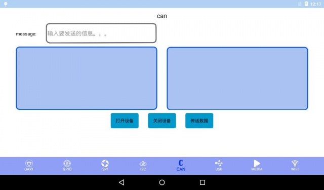
| + | ###**五.can测试** |
| − | === '''测试说明(test instruction)''' ===
| + | 测试之前需要连接 CAN 的管脚,将 CAN1 的 CAN_L 和 CAN2 的 CAN_L 连接,将 CAN1 的 CAN_H 和 CAN2 的 CAN_H 连接。 |
| − | (1)测试音频和视频的功能。<br>
| + | [[文件:Android test 1.6.jpg|640px]] |
| − | <span style="background:#CCCCCC">test functions of audio and vedio。</span>
| + | |
| − | === '''测试方法(test method)''' ===
| + | *测试方法: |
| − | (1)点击“Audio/video”按钮,启动测试程序。<br>
| + | 1)点击打开设备 |
| − | <span style="background:#CCCCCC">click“Audio/video”button,to boot test program。</span><br>
| + | 2)输入要发送的内容,长度不超过8 |
| − | [[文件:Android test 2.7.2.jpg|640px]]<br> | + | 3)点击传送数据 |
| − | (2)插上耳机,点击“Play_music”,可以听到一段音乐。<br>
| + | 4)点击关闭设备 |
| − | <span style="background:#CCCCCC">wear earphone,click“Play_music”,can hear a piece of music。</span><br>
| |
| − | (3)点击“Play_video”,播放一段视频。<br>
| |
| − | <span style="background:#CCCCCC">click“Play_video”,to play a piece of vedio。</span><br>
| |
| − | [[文件:Android test 2.7.2 2.jpg|640px]]<br>
| |
| − | (4)测试完成,退出测试程序。<br>
| |
| − | <span style="background:#CCCCCC">test is over,exit test program。</span><br>
| |
| | | | |
| − | == '''GPIO(GPIO test)''' ==
| + | ###**六.Usb测试** |
| − | === '''测试说明(test instruction)''' ===
| + | 查看usb跟sd卡里的内容 |
| − | (1)测试GPIO的功能。<br>
| + | [[文件:Android test 1.7.jpg|640px]] |
| − | <span style="background:#CCCCCC">test functions of GPIO。</span>
| |
| − | === '''测试方法(test method)''' ===
| |
| − | (1)1.在output1或output2下拉框选择要测试的GPIO端口。<br>
| |
| − | <span style="background:#CCCCCC">Click and select the GPIO port to test in the output1 or output2 drop-down box。</span><br>
| |
| − | [[文件:Android test 2.7.2 3.png|640px]]<br> | |
| − | (2)2.点击output1可以控制左边端口的电平,output2可以控制右边端口的电平。<br>
| |
| − | <span style="background:#CCCCCC">Click the button named“output1“ to control the level of the left port, and click the button named "output2" can control the level of the right port。</span><br>
| |
| − | (3)点击左边的1可以把output1的电平拉高,点击左边的0可以把电平拉低同理点击右边的数字可以控制output2的电平。<br>
| |
| − | <span style="background:#CCCCCC"> Click the "1" in the left side can make "output1" be high level, click the 0 in the left side can make "output1" be low level. You also can click on the right side of the figure to control the level of "output2" as well。</span><br>
| |
| | | | |
| | + | ###**七.media测试** |
| | + | 测试前要自备视频 |
| | + | [[文件:Android test 1.8.jpg|640px]] |
| | + | |
| | + | *测试方法: |
| | + | 1)选择一个视频 |
| | + | 2)播放视频 |
| | | | |
| − | == '''产品介绍(product instroduction)''' ==
| + | ###**八.Wifi测试** |
| − | === '''产品图片(product photo)''' ===
| + | [[文件:Android test 1.9.jpg|640px]] |
| − | (1)点击“Product”按钮,可以看到我司产品图片介绍,左右滑动屏幕能了解更多。<br>
| + | *测试方法: |
| − | <span style="background:#CCCCCC">click“Product”button,you can see the instruduction and photo of our products,left or right sliding screen for more information。</span><br>
| + | 1)点击wifi开关打开wifi,等待wifi搜索结果 |
| − | [[文件:Android test 2.8.1.png|640px]]<br> | + | 2)点击要连接的wifi |
| | + | 3)输入密码,点击连接按钮 |
测试之前需要连接 CAN 的管脚,将 CAN1 的 CAN_L 和 CAN2 的 CAN_L 连接,将 CAN1 的 CAN_H 和 CAN2 的 CAN_H 连接。