|
|
| (未显示同一用户的3个中间版本) |
| 第1行: |
第1行: |
| | <div> | | <div> |
| | | | |
| − | = '''准备开发板套件(prepare development board kits)''' = | + | = '''准备开发板套件''' = |
| | ---- | | ---- |
| | 开发板套件由开发板和开发板配件组成。<br> | | 开发板套件由开发板和开发板配件组成。<br> |
| − | <span style="background:#CCCCCC">Development board kits consist of development board and its accessories.<br>
| + | == '''开发板''' == |
| − | == '''开发板(development board)''' == | |
| | 开发板由以下器件组装而成:<br> | | 开发板由以下器件组装而成:<br> |
| − | <span style="background:#CCCCCC">Development board consist of following components:<br>
| |
| | | | |
| − | * MY-RK3288-CB314(核心板) 一片<br> | + | * MYZR-RK3288-CB314(核心板) 一片<br> |
| − | * <span style="background:#CCCCCC"> MY-RK3288-CB314 (core board),one unit<br>
| |
| | | | |
| − | * MY-RK3288-MB314(底板) 一片<br> | + | * MYZR-RK3288-MB314(底板) 一片<br> |
| − | * <span style="background:#CCCCCC"> MY-RK3288-MB314 (bottom board),one unit<br>
| |
| | | | |
| | * 显示屏电路板一片<br> | | * 显示屏电路板一片<br> |
| − | *<span style="background:#CCCCCC"> Circuit board of screen panel,one unit<br>
| |
| | | | |
| | * 液晶显示屏一块<br> | | * 液晶显示屏一块<br> |
| − | * <span style="background:#CCCCCC">Crystal liquid screen,one piece<br>
| |
| | | | |
| | * 触摸屏一片<br> | | * 触摸屏一片<br> |
| − | *<span style="background:#CCCCCC"> Touch screen,one unit<br>
| |
| | | | |
| − | == '''开发板配件(development board accessory)''' == | + | == '''开发板配件''' == |
| | | | |
| | 开发板配件有:<br> | | 开发板配件有:<br> |
| − | <span style="background:#CCCCCC">development board accessories include: <br>
| |
| | | | |
| | * 电源适配器1个<br> | | * 电源适配器1个<br> |
| − | *<span style="background:#CCCCCC"> adaptor,one unit<br>
| |
| | | | |
| | * USB下载线1条<br> | | * USB下载线1条<br> |
| − | *<span style="background:#CCCCCC"> USB download cable,one piece<br>
| |
| | | | |
| | * 网线1条<br> | | * 网线1条<br> |
| − | *<span style="background:#CCCCCC"> internet cable,one piece<br>
| |
| | | | |
| | * 串口线1条<br> | | * 串口线1条<br> |
| − | *<span style="background:#CCCCCC">serial line,one piece<br>
| |
| | | | |
| − | = '''开发板接口概览(overview of development board interface)''' = | + | = '''开发板接口概览''' = |
| | ---- | | ---- |
| − | 在启动开发板之前我们需要认识一些接口,并将这些接口正确连接到计算机。这里我先认识MY-RK3288-MB314的接口。<br>
| + | 在启动开发板之前我们需要认识一些接口,并将这些接口正确连接到计算机。这里我先认识MYZR-RK3288-MB314的接口。<br> |
| − | <span style="background:#CCCCCC"> Before starting the development board, we need to recognize some interfaces and connect them to the computer correctly.Here I first know the interface of MY-RK3288-MB314 .<br>
| |
| | | | |
| − | MY-R3288-MB314 正面图(MY-R3288-MB314 front view):<br>
| + | ===MYZR-R3288-MB314 正面图=== |
| − | [[文件:myrk3288_mb314_1.1.0.1.jpg|642px]]<br> | + | [[文件:myrk3288_mb314_1.1.0.1.jpg|1000px]]<br> |
| − | MY-R3288-MB314 背面图(MY-R3288-MB314 rear view):<br>
| + | ===MYZR-R3288-MB314 背面图=== |
| − | [[文件:myrk3288_mb314_1.2.0.1.jpg|642px]]<br> | + | [[文件:myrk3288_mb314_1.2.0.1.jpg|1000px]]<br> |
| | | | |
| − | = '''快速启动开发板(fast boot development board)''' = | + | = '''快速启动开发板''' = |
| | ---- | | ---- |
| | 1)跳到“开发板与计算机的连接”那一节中“关闭电源开关”,“连接电源线”操作。<br> | | 1)跳到“开发板与计算机的连接”那一节中“关闭电源开关”,“连接电源线”操作。<br> |
| − | 1)<span style="background:#CCCCCC"> skip to "off power switch" and "connect power line" in the section "connection between development board and computer". <br>
| |
| | | | |
| | 2)跳到“开发板的启动”那一节中的“为开发板上电”,从那开始继续操作。<br> | | 2)跳到“开发板的启动”那一节中的“为开发板上电”,从那开始继续操作。<br> |
| − | 2)<span style="background:#CCCCCC"> skip to "power the development board" in the section "start the development board" and proceed from there. <br>
| |
| | | | |
| | 说明:快速启动方式下,开发板与计算机没有连接,但是从液晶屏上是可以看出系统启动状态的。<br> | | 说明:快速启动方式下,开发板与计算机没有连接,但是从液晶屏上是可以看出系统启动状态的。<br> |
| − | <span style="background:#CCCCCC">Note: the development board is not connected to the computer in the fast start mode, but the system start state can be seen from the LCD screen.<br>
| |
| | | | |
| − | == '''开发板与计算机的连接( development board is connected to the computer)''' == | + | == '''开发板与计算机的连接''' == |
| | + | |
| | 由于在很多情况下我们需要连接开发板与计算机,下面内容将描述开发板与计算机的连接方式。<br> | | 由于在很多情况下我们需要连接开发板与计算机,下面内容将描述开发板与计算机的连接方式。<br> |
| − | <span style="background:#CCCCCC">Because in many cases we need to connect the development board to the computer, the following describes how the development board connects to the computer.<br>
| |
| | | | |
| − | === '''关闭电源开关(Power switch off)''' === | + | === '''关闭电源开关''' === |
| | 1) 在连接开发板与计算机之前,我们需要检查开发板电源开关状态,并确保电源开关是断开状态。<br> | | 1) 在连接开发板与计算机之前,我们需要检查开发板电源开关状态,并确保电源开关是断开状态。<br> |
| − | 1)<span style="background:#CCCCCC">Before connecting the development board to the computer, we need to check the power switch status of the development board and ensure that the power switch is disconnected.<br>
| |
| | | | |
| | 2) 使开发板电源开关处于断开的方式是:将开发板电源开关(开发板正面图的图示MAIN POWER SW)按到断开状态(—:闭合,O:断开)。<br> | | 2) 使开发板电源开关处于断开的方式是:将开发板电源开关(开发板正面图的图示MAIN POWER SW)按到断开状态(—:闭合,O:断开)。<br> |
| − | 2)<span style="background:#CCCCCC">The way to keep the POWER switch on the development board in a disconnected state is to press the POWER switch on the development board (the MAIN POWER SW shown in the drawing on the front of the development board) to a disconnected state (-- : close, O: disconnect).<br>
| |
| | | | |
| − | === '''串口线的连接(Connection of serial lines)''' === | + | === '''串口线的连接''' === |
| | 将串口线一端连接到开发板的正面图DEBUG UART接口,一端连接到计算机。<br> | | 将串口线一端连接到开发板的正面图DEBUG UART接口,一端连接到计算机。<br> |
| − | <span style="background:#CCCCCC">Connect one end of the serial port line to the DEBUG UART interface on the front of the development board, and the other end to the computer.<br>
| |
| | | | |
| − | 说明(Introductions):
| + | 说明:<br> |
| | 1)如果计算机没有串口,则需要自行准备USB转串口线并连接。<br> | | 1)如果计算机没有串口,则需要自行准备USB转串口线并连接。<br> |
| − | 1)<span style="background:#CCCCCC">If the computer does not have a serial port, you need to prepare your own USB cable and connect it.<br>
| |
| | | | |
| | 2)如果没有连接串口线,将不能通过串口方式与开发板交互。但是不影响开发板的启动及烧录系统。<br> | | 2)如果没有连接串口线,将不能通过串口方式与开发板交互。但是不影响开发板的启动及烧录系统。<br> |
| − | 2)<span style="background:#CCCCCC">If there is no connection to the serial port line, you will not be able to interact with the development board in a serial port manner.However, it does not affect the starting and burning system of the development board.<br>
| |
| | | | |
| − | == '''串口终端工具配置(Serial port terminal tool configuration)''' == | + | == '''串口终端工具配置''' == |
| | | | |
| | 1)通过Windows的设备管理器找到计算机上我们使用端口号。<br> | | 1)通过Windows的设备管理器找到计算机上我们使用端口号。<br> |
| − | 1)<span style="background:#CCCCCC">Find the port number we use on the computer through the Windows device manager.<br>
| |
| | | | |
| | 2)配置串口终端工具的各参数。<br> | | 2)配置串口终端工具的各参数。<br> |
| − | 2)<span style="background:#CCCCCC">Configure the parameters of the serial port terminal tool.<br>
| |
| | | | |
| | SecureCRT & USB串口3 示例配置如下:<br> | | SecureCRT & USB串口3 示例配置如下:<br> |
| − | <span style="background:#CCCCCC">The SecureCRT & USB serial port 3 example configuration is as follows:<br>
| |
| | | | |
| | [[文件:myrk3288_EK314_3.2.0.1.jpg|642px]]<br> | | [[文件:myrk3288_EK314_3.2.0.1.jpg|642px]]<br> |
| | | | |
| − | == '''网线的连接(Network connection)''' == | + | == '''网线的连接''' == |
| | | | |
| | 将网线一端连接到开发板的正面图的1000M Ethernet 或10M/100M Ethernet接口,网线另一端插入计算机的网口。<br> | | 将网线一端连接到开发板的正面图的1000M Ethernet 或10M/100M Ethernet接口,网线另一端插入计算机的网口。<br> |
| − | <span style="background:#CCCCCC">Connect one end of the wire to the 1000M or 10M/100M Ethernet interface on the front of the development board, and insert the other end of the wire into the computer's network port.<br>
| |
| | | | |
| − | == '''USB下载线的连接(USB download the connection)''' == | + | == '''USB下载线的连接''' == |
| | | | |
| | 将USB线一端连接到开发板的正面图OTG接口,另外一端插入计算机的USB接口。<br> | | 将USB线一端连接到开发板的正面图OTG接口,另外一端插入计算机的USB接口。<br> |
| − | <span style="background:#CCCCCC">Connect one end of the USB cable to the OTG interface on the front of the development board, and insert the other end into the USB interface of the computer.<br>
| |
| | | | |
| − | == '''连接电源线(Connect the power cord)''' == | + | == '''连接电源线''' == |
| | | | |
| | 将电源线一端连接到开发板的正面图DC_5V_IN接口,一端连接电源插座。<br> | | 将电源线一端连接到开发板的正面图DC_5V_IN接口,一端连接电源插座。<br> |
| − | <span style="background:#CCCCCC">Connect one end of the power cord to the DC_5V_IN interface on the front of the development board, and one end to the power socket.<br>
| |
| | | | |
| − | == '''开发板的启动(Start the development board)''' == | + | == '''开发板的启动''' == |
| | 1)在“开发板与计算机的连接”中按照顺序进行操作后,我们的开发板与计算机的连接已经完成了。<br> | | 1)在“开发板与计算机的连接”中按照顺序进行操作后,我们的开发板与计算机的连接已经完成了。<br> |
| − | 1)<span style="background:#CCCCCC">After working in sequence in "development board to computer connection", our development board to computer connection has been completed.<br>
| |
| | | | |
| | 2)要使开发板启动,我们需要为开发板上电。<br> | | 2)要使开发板启动,我们需要为开发板上电。<br> |
| − | 2)<span style="background:#CCCCCC"> to enable the development board to start up, we need to power the development board.<br>
| |
| | | | |
| | 3)将开发板电源开关开发板正面图MAIN POWER SW按到闭合状态(—:闭合,O:断开)。<br> | | 3)将开发板电源开关开发板正面图MAIN POWER SW按到闭合状态(—:闭合,O:断开)。<br> |
| − | 3)<span style="background:#CCCCCC">Press the MAIN POWER SW to the closed state (-- : close, O: disconnect) on the front of the development board POWER switch.<br>
| |
| | | | |
| | 4)然后按住开发板正面图SLEEP WAKE按钮直到开发板的LED灯亮起来为止。<br> | | 4)然后按住开发板正面图SLEEP WAKE按钮直到开发板的LED灯亮起来为止。<br> |
| − | 4)<span style="background:#CCCCCC">Then hold down the SLEEP WAKE button on the front of the development board until the LED light of the development board lights up.<br>
| |
| | | | |
| − | == '''观察启动状况(observe booting condition)''' == | + | == '''观察启动状况''' == |
| | | | |
| − | === '''串口终端动态(serial port terminal dynamics)''' === | + | === '''串口终端动态''' === |
| | | | |
| | 会看到计算机的串口终端有开发板启动过程中输出的启动过程信息。<br> | | 会看到计算机的串口终端有开发板启动过程中输出的启动过程信息。<br> |
| − | <span style="background:#CCCCCC">you can see the information about booting process outputed during the course of development board booting through serial port terminal。<br>
| |
| | | | |
| | 启动串口打印信息如下:<br> | | 启动串口打印信息如下:<br> |
| − | <span style="background:#CCCCCC">After starting, the serial port printing information is as follows:<br>
| |
| | | | |
| | [[文件:MY-R3288-EK314_3.7.1.1.png|642px]]<br> | | [[文件:MY-R3288-EK314_3.7.1.1.png|642px]]<br> |
| | | | |
| − | === '''显示屏状态(Display status)''' === | + | === '''显示屏状态''' === |
| | | | |
| | 如果液晶显示屏正确连接,会看到在开发板的启动过程中显示屏有输出图像。<br> | | 如果液晶显示屏正确连接,会看到在开发板的启动过程中显示屏有输出图像。<br> |
| − | <span style="background:#CCCCCC">If the LCD is properly connected, you will see an output image of the display during the startup of the development board.<br>
| |
| | | | |
| | </div> | | </div> |
准备开发板套件
开发板套件由开发板和开发板配件组成。
开发板
开发板由以下器件组装而成:
- MYZR-RK3288-CB314(核心板) 一片
开发板配件
开发板配件有:
开发板接口概览
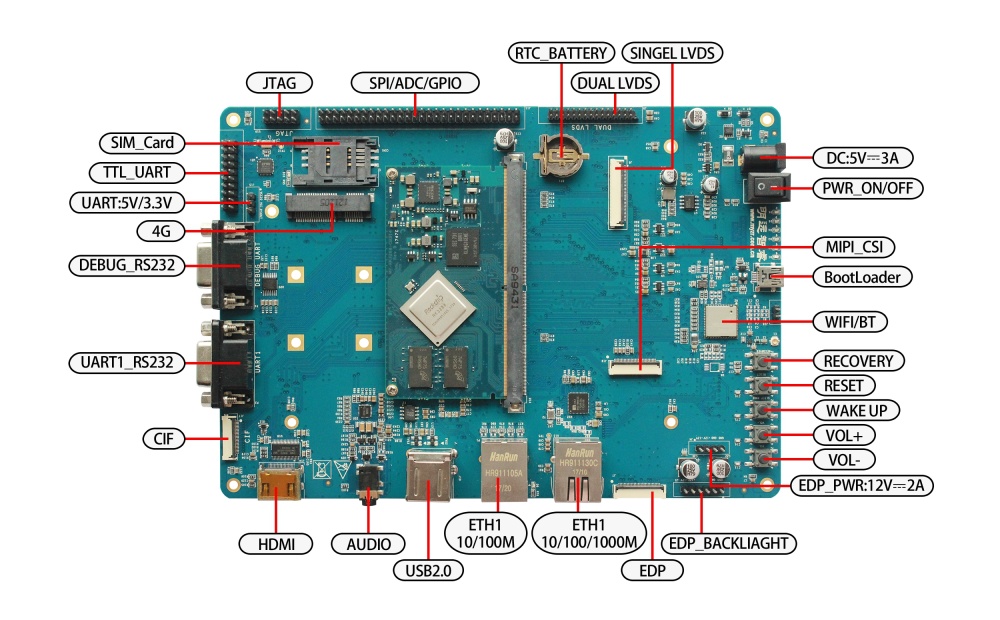
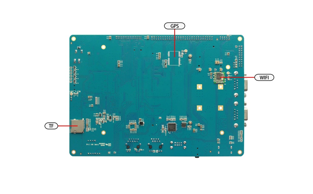
在启动开发板之前我们需要认识一些接口,并将这些接口正确连接到计算机。这里我先认识MYZR-RK3288-MB314的接口。
MYZR-R3288-MB314 正面图

MYZR-R3288-MB314 背面图

快速启动开发板
1)跳到“开发板与计算机的连接”那一节中“关闭电源开关”,“连接电源线”操作。
2)跳到“开发板的启动”那一节中的“为开发板上电”,从那开始继续操作。
说明:快速启动方式下,开发板与计算机没有连接,但是从液晶屏上是可以看出系统启动状态的。
开发板与计算机的连接
由于在很多情况下我们需要连接开发板与计算机,下面内容将描述开发板与计算机的连接方式。
关闭电源开关
1) 在连接开发板与计算机之前,我们需要检查开发板电源开关状态,并确保电源开关是断开状态。
2) 使开发板电源开关处于断开的方式是:将开发板电源开关(开发板正面图的图示MAIN POWER SW)按到断开状态(—:闭合,O:断开)。
串口线的连接
将串口线一端连接到开发板的正面图DEBUG UART接口,一端连接到计算机。
说明:
1)如果计算机没有串口,则需要自行准备USB转串口线并连接。
2)如果没有连接串口线,将不能通过串口方式与开发板交互。但是不影响开发板的启动及烧录系统。
串口终端工具配置
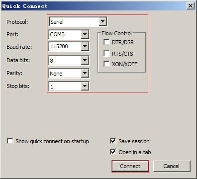
1)通过Windows的设备管理器找到计算机上我们使用端口号。
2)配置串口终端工具的各参数。
SecureCRT & USB串口3 示例配置如下:

网线的连接
将网线一端连接到开发板的正面图的1000M Ethernet 或10M/100M Ethernet接口,网线另一端插入计算机的网口。
USB下载线的连接
将USB线一端连接到开发板的正面图OTG接口,另外一端插入计算机的USB接口。
连接电源线
将电源线一端连接到开发板的正面图DC_5V_IN接口,一端连接电源插座。
开发板的启动
1)在“开发板与计算机的连接”中按照顺序进行操作后,我们的开发板与计算机的连接已经完成了。
2)要使开发板启动,我们需要为开发板上电。
3)将开发板电源开关开发板正面图MAIN POWER SW按到闭合状态(—:闭合,O:断开)。
4)然后按住开发板正面图SLEEP WAKE按钮直到开发板的LED灯亮起来为止。
观察启动状况
串口终端动态
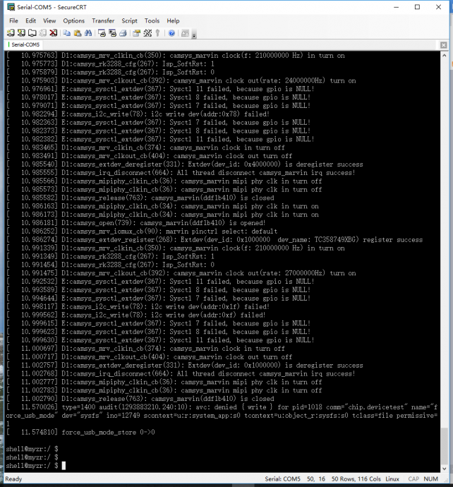
会看到计算机的串口终端有开发板启动过程中输出的启动过程信息。
启动串口打印信息如下:

显示屏状态
如果液晶显示屏正确连接,会看到在开发板的启动过程中显示屏有输出图像。


