“MYZR-SAMA5-MB200 Hardware manual”的版本间的差异
来自明远智睿的wiki
(→MY-SAMA5-EK200 view) |
小 (Admin移动页面MY-SAMA5-MB200 Hardware manual至MYZR-SAMA5-MB200 Hardware manual,不留重定向) |
||
| (未显示同一用户的1个中间版本) | |||
| 第1行: | 第1行: | ||
<div> | <div> | ||
| − | = ''' | + | = '''MYZR-SAMA5-EK200 view''' = |
---- | ---- | ||
== '''Front view''' == | == '''Front view''' == | ||
2020年10月22日 (四) 17:25的最新版本
目录
- 1 MYZR-SAMA5-EK200 view
- 2 Description of interfaces
MYZR-SAMA5-EK200 view
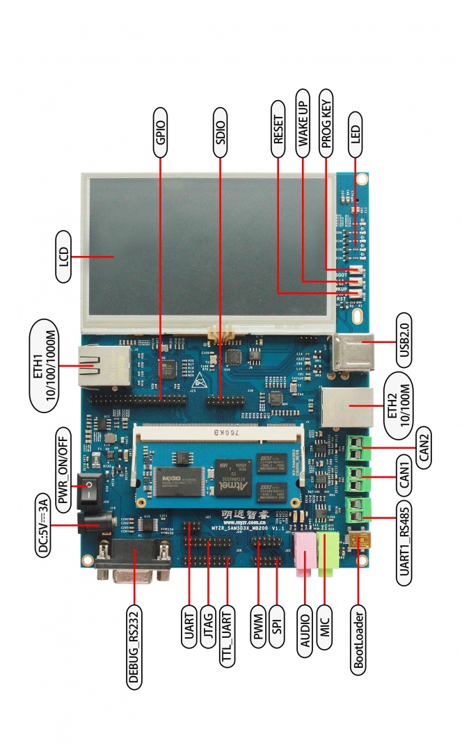
Front view
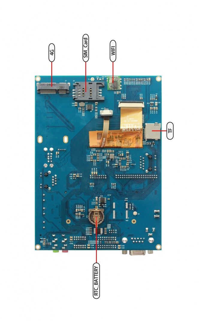
Rear view
Description of interfaces
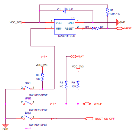
Key
| Silk screen | Signal | Function | Description |
|---|---|---|---|
| SW1 | NRST | Device reset | Press device reset |
| SW2 | WKUP | Wake up | Boot mode contrl |
| SW3 | BOOT_CS_OFF | Boot mode contrl | Press to generate wake up signal |
USB download port
| Silk screen | Signal | Function | Description |
|---|---|---|---|
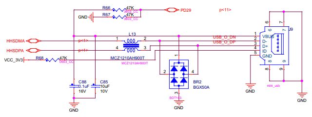
| J9 | HHSDMA,HHSDPA | Programming interface | After device is entered into mode of download,programming will be done via this interface) |
USB interface
USB-B & USB3
| Silk screen | Signal | Function | Description |
|---|---|---|---|
| U10 | HHSDPB,HHSDMB | (USB HUB chip) | USB2514 is expanded to 3 USB ports and 1 3G USB port |
| J11 | USBDN_DP3,USBDN_DM3 | USB | USB socket port |
USB1 & USB2
| Silk screen | Signal | Function | Description |
|---|---|---|---|
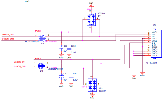
| J10[1~4] | USBDN_DP2,USBDN_DM2 | USB | USB port |
| J10[5~8] | USBDN_DP1,USBDN_DM1 | USB | USB port |
USB WIFI module
| Silk screen | Signal | Function | Description |
|---|---|---|---|
| U11 | HHSDPC,HHSDMC | USB-WIFI | USB-C is used as USB-WIFI(RTL8188EUS) interface |
LCD、backlight and touch screen
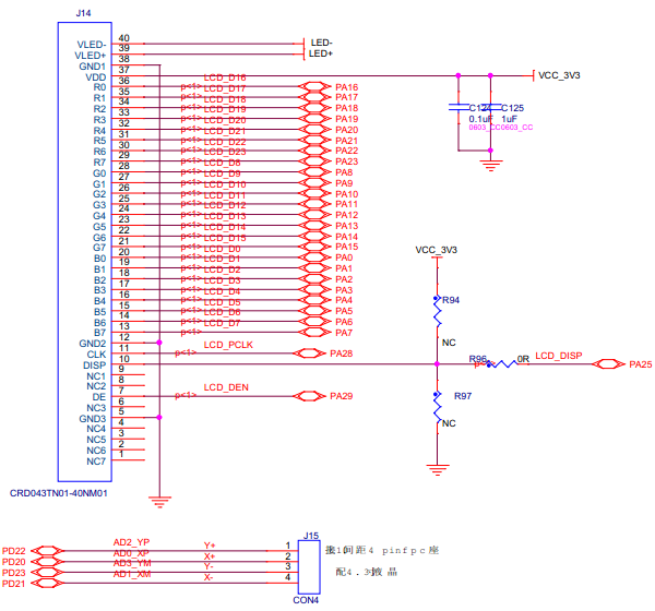
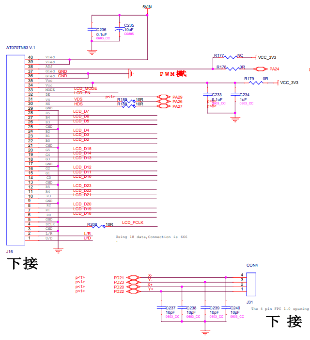
LCD has two groups of interfaces,these two groups of interfaces share the same group of signal。one group support 24bit,another group support 18bit(24 data bit can be compatible to these two groups of interfaces).
24bit LCD display and touch screen interface
| Silk screen | Signal | Function | Description |
|---|---|---|---|
| J14 | PA* | LCD interface | 24bit LCD display touch screen interface |
| J15 | PD20~PD23 | touch screen interface | 4thread resistance touch screen interface |
18bit LCD touch screen interface
| Silk screen | Signal | Function | Description |
|---|---|---|---|
| J16 | PA* | LCD interface) | 18bit LCD display screen interface |
| J31 | PD20~PD23 | touch screen interface | 18bit LCD display screen interface |
Backlight control
| Silk screen | Signal | Function | Description |
|---|---|---|---|
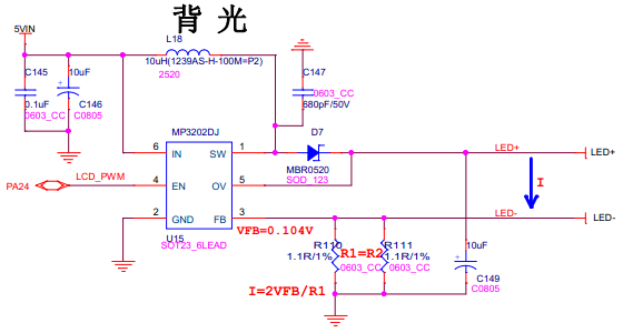
| MP3202DJ | PA24(LCD_PWM) | LCD backlight regulation | LCD backlight brightness adjustment |
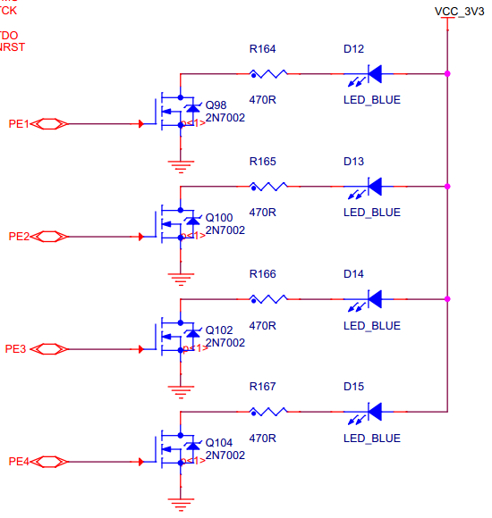
LED interface
| Silk screen | Signal | Function | Description |
|---|---|---|---|
| D12 | PE1 | GPIO-LED | The LED is realized to solid lit after kernel booting |
| D13 | PE2 | GPIO-LED | LED is realized to flash when CPU is working normally |
| D14 | PE3 | GPIO-LED | It is realized to be as universial GPIO-LED,users can control on/off of the LED in the system |
| D15 | PE4 | GPIO-LED | It is realized as GPIO-TIMER,which can regulate holding time of high/low electrical level in the system |
Instruction:LED multiplex the 4 pins of EBI(e.g if want to use EBI,then PE1~PE4 can't work sa LED)
Serial port
Debug serial port
| Silk screen | Signal | Function | Description |
|---|---|---|---|
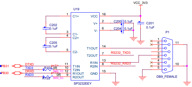
| P1 | DTXD,DRXD | Debug serial port | Used for system information output, system control command input |
USART&UART
| Silk screen | Signal | Function | Description |
|---|---|---|---|
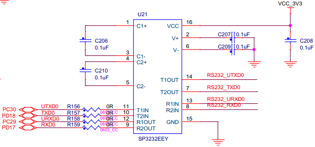
| U21(9,10) | TXD0,RXD0 | USART0 | USART0 signal |
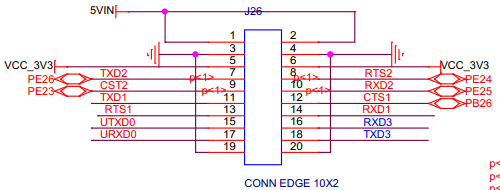
| J26(11~14) | TXD1,RTS1,CTS1,RXD1 | USART1 | USART pin interface |
| J26(7~10) | TXD2,RTS2,CTS2,RXD2 | USART2 | USART pin interface |
| J26(16,18) | RXD3,TXD3 | USART3 | USART pin interface |
| J26(15,17) | UTXD0,URXD0 | UART0 | USART pin interface |
RS232
| Silk screen | Signal | Function | Description |
|---|---|---|---|
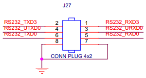
| J27(1,2) | RS232_RXD3, RS232_TXD3 | RS232 | USART3 is multiplexed as RS232 |
| J27(3,4) | RS232_URXD0, RS232_UTXD0 | RS232 | UART0 is multiplexed as RS232 |
| J27(5,6) | RS232_TXD0, RS232_RXD0 | RS232 | UART0 is multiplexed as RS232 |
RS485
| Silk screen | Signal | Function | Description |
|---|---|---|---|
| J25 | RS485_2_RX-,RS485_2_TX- | RS485 | USART1 is multiplexed as RS485 |
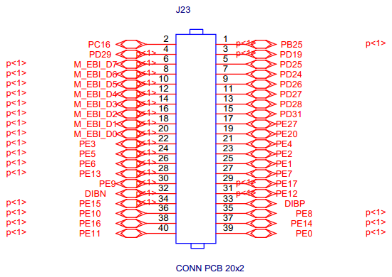
EBI
| Silk screen | Signal | Function | Description |
|---|---|---|---|
| J23 | D0~D7 | EBI data line | Infterface of external bus |
| PE0~PE20 | EBI address line |
Description: the PE1~PE4 of EBI is implemented as LED. If you want to use EBI, you need to reconfigure PE1~PE4.
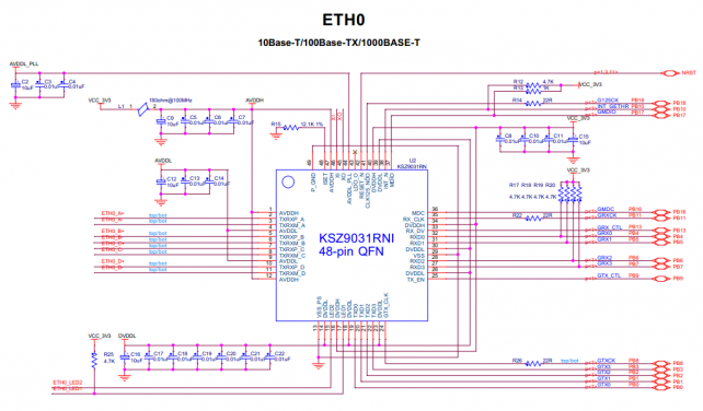
Gbps ethernet
Interface silk screen: J2
Chip silk screen: U2
Chip model: KSZ9031RN
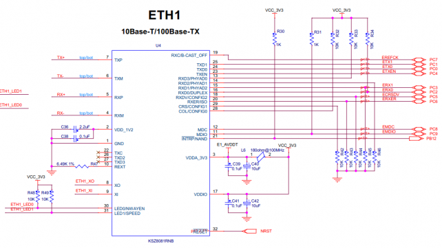
Mbps ethernet
Interface silk screen:J3
Chip silk screen:U4
Chip model:KSZ8081RNB
SD port
CAN0 interface
CAN1 interface
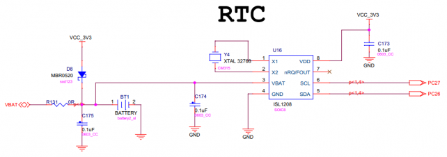
RTC
Use external RTC
Chip silk screen:U16。
Chip model:ISL1208
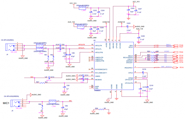
Audio(WM8904)
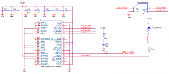
PCI-E
PCI-EInterface silk screen:J7
SIM Card Interface silk screen:J6
GPS
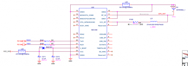
Chip silk screen:U22
Module model:NEO-6M
