“MYZR-IMX6-EK200 Android-5.1.1 Test Manual”的版本间的差异
来自明远智睿的wiki
(创建页面,内容为“<div> = '''Applicable scope''' = 640px<br> = '''Test project''' = == '''UART test''' == === '''Test instruction''' === (1)Total...”) |
|||
| 第1行: | 第1行: | ||
| − | + | [^_^]: MY-IMX Android-5.1.1 Test Manual | |
| − | + | ## **Applicable scope** | |
| + | [[File:Android test 1.jpg|640px]] | ||
| + | ## **Test project** | ||
| + | ### I.)uart Test | ||
| + | Before testing, you need to short the serial port's transceiver pin. The pins of different development boards are different. The corresponding relationship is as follows: | ||
| + | [[File:Android test 1.2.jpg|640px]] | ||
| + | |||
| + | * Test method: | ||
| + | 1)Select the serial port to test, set the baud rate | ||
| + | 2)Click on the device button | ||
| + | 3)Enter the content to send | ||
| + | 4)Click the Transfer Data button | ||
| + | 5)Click the Close Device button | ||
| − | [[File:Android test 1.jpg|640px]] | + | ###**II.)Gpio Test** |
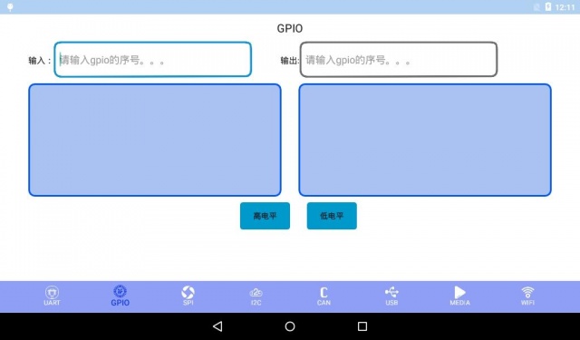
| + | [[File:Android test 1.3.jpg|640px]] | ||
| − | + | * Test method: | |
| − | + | 1)Input: Enter a GPIO set to input pin | |
| − | + | 2)Output: Enter a GPIO set to the output pin | |
| + | 3)Click the high/low level button to set the level | ||
| + | 4)Test the output pin level with a multimeter | ||
| + | ###**Iii.)Spi Test** | ||
| + | Before the test, the pins of the SPI need to be short-connected. The pins of the short connections of different development boards are different. The corresponding relationships are as follows: | ||
| + | [[File:Android test 1.4.jpg|640px]] | ||
| + | |||
| + | * Test method: | ||
| + | 1)Click on the device button | ||
| + | 2)Enter what you want to send | ||
| + | 3)Click the data transfer button | ||
| + | 4)Click the Close Device button | ||
| + | |||
| + | ###**Iv. )I2C Test ** | ||
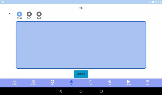
| + | [[File:Android test 1.5.jpg|640px]] | ||
| − | + | * Test method: | |
| − | + | 1)Select I2C bus to test | |
| − | + | 2)Click to read I2C button to read the device on the bus | |
| − | |||
| − | |||
| − | |||
| − | |||
| − | + | ###**V.) Can Test** | |
| − | + | Before testing, it is necessary to connect CAN pins, connect CAN _ L of CAN 1 with CAN _ L of CAN 2, and connect CAN _ H of CAN 1 with CAN _ H of CAN 2. | |
| − | + | [[File:Android test 1.6.jpg|640px]] | |
| − | |||
| − | |||
| − | |||
| − | |||
| − | |||
| − | |||
| − | |||
| − | |||
| − | |||
| − | |||
| − | |||
| − | |||
| − | |||
| − | |||
| − | |||
| − | |||
| − | |||
| − | |||
| − | |||
| − | |||
| − | |||
| − | |||
| − | |||
| − | [[File:Android test | ||
| − | + | * Test method: | |
| − | + | 1)Click on Open Device | |
| − | + | 2)Enter the content to send, not more than 8 | |
| − | + | 3)Click to transmit data | |
| − | + | 4)Click to close device | |
| − | |||
| − | |||
| − | |||
| − | + | ###**VI.) Usb test** | |
| + | Check the USB and SD cards. | ||
| + | [[File:Android test 1.7.jpg|640px]] | ||
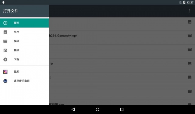
| − | + | ###**VII.) media Test** | |
| − | + | Bring your own video before testing. | |
| − | + | [[File:Android test 1.8.jpg|640px]] | |
| − | |||
| − | |||
| − | |||
| − | |||
| − | |||
| − | |||
| − | |||
| − | [[File:Android test | ||
| − | + | *Test methods: | |
| − | + | 1)Select a video | |
| − | + | 2)Play Video | |
| − | |||
| − | |||
| − | |||
| − | |||
| − | |||
| − | |||
| − | |||
| − | |||
| − | |||
| − | |||
| − | |||
| − | |||
| − | |||
| − | |||
| − | |||
| − | |||
| − | |||
| − | |||
| − | |||
| − | |||
| − | |||
| − | |||
| − | |||
| − | |||
| − | |||
| − | |||
| − | |||
| − | |||
| − | |||
| − | |||
| − | |||
| − | |||
| − | |||
| − | |||
| − | |||
| − | |||
| − | |||
| − | |||
| − | |||
| − | |||
| − | |||
| − | |||
| − | |||
| − | |||
| − | |||
| − | |||
| − | |||
| − | |||
| − | |||
| − | |||
| − | |||
| − | |||
| − | |||
| − | |||
| − | |||
| − | |||
| − | |||
| − | |||
| − | |||
| − | |||
| − | |||
| − | |||
| − | |||
| − | |||
| − | |||
| − | |||
| − | |||
| − | |||
| − | |||
| − | |||
| − | |||
| − | |||
| − | |||
| − | |||
| − | |||
| − | |||
| − | |||
| − | |||
| − | |||
| − | |||
| − | |||
| − | |||
| − | |||
| − | |||
| − | |||
| − | |||
| − | |||
| − | |||
| − | |||
| − | |||
| − | |||
| − | |||
| − | |||
| − | |||
| − | |||
| − | |||
| − | |||
| − | |||
| − | |||
| − | |||
| − | |||
| − | |||
| − | |||
| − | |||
| − | |||
| − | |||
| − | |||
| − | |||
| − | |||
| − | |||
| − | |||
| − | |||
| − | |||
| − | |||
| − | |||
| − | |||
| − | |||
| − | |||
| − | |||
| − | |||
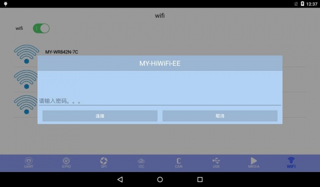
| − | + | ###**VIII.) Wifi Test** | |
| + | [[File:Android test 1.9.jpg|640px]] | ||
| + | *Test methods: | ||
| + | 1)Click the WiFi switch to turn on WiFi and wait for WiFi search results | ||
| + | 2)Click the WiFi you want to connect to | ||
| + | 3)Enter password, click the connection button | ||
2019年1月8日 (二) 14:34的版本
目录
Applicable scope
Test project
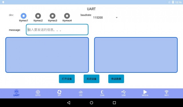
I.)uart Test
Before testing, you need to short the serial port's transceiver pin. The pins of different development boards are different. The corresponding relationship is as follows:
- Test method:
1)Select the serial port to test, set the baud rate
2)Click on the device button
3)Enter the content to send
4)Click the Transfer Data button
5)Click the Close Device button
II.)Gpio Test
- Test method:
1)Input: Enter a GPIO set to input pin 2)Output: Enter a GPIO set to the output pin 3)Click the high/low level button to set the level
4)Test the output pin level with a multimeter
Iii.)Spi Test
Before the test, the pins of the SPI need to be short-connected. The pins of the short connections of different development boards are different. The corresponding relationships are as follows:

- Test method:
1)Click on the device button
2)Enter what you want to send
3)Click the data transfer button
4)Click the Close Device button
**Iv. )I2C Test **
- Test method: 1)Select I2C bus to test 2)Click to read I2C button to read the device on the bus
V.) Can Test
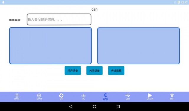
Before testing, it is necessary to connect CAN pins, connect CAN _ L of CAN 1 with CAN _ L of CAN 2, and connect CAN _ H of CAN 1 with CAN _ H of CAN 2.
- Test method:
1)Click on Open Device
2)Enter the content to send, not more than 8
3)Click to transmit data
4)Click to close device
VI.) Usb test
VII.) media Test
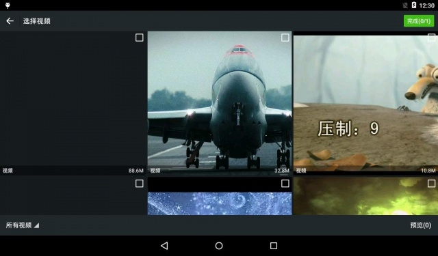
Bring your own video before testing.
- Test methods:
1)Select a video
2)Play Video
VIII.) Wifi Test
- Test methods:
1)Click the WiFi switch to turn on WiFi and wait for WiFi search results
2)Click the WiFi you want to connect to
3)Enter password, click the connection button

