“MYZR-RK3399-EK314 Linux-4.4 Test Manual”的版本间的差异
(创建页面,内容为“ [^_^]: MY-RK3399-EK314 linux4.4 Test Manual <br> ## **Part 1 Test Instructions** Development board user name: myzr Password: myzr root User password: root<...”) |
|||
| 第8行: | 第8行: | ||
## **Part 2 Interface Test ** | ## **Part 2 Interface Test ** | ||
### Ethernet test | ### Ethernet test | ||
| − | The | + | The MYZR-RK3399 evaluation board has a Gigabit Ethernet port. <br> |
{| class="wikitable" | {| class="wikitable" | ||
! style="color:white; background:#003399;" |Evaluation model | ! style="color:white; background:#003399;" |Evaluation model | ||
| 第15行: | 第15行: | ||
! style="color:white; background:#003399;" |System Interface | ! style="color:white; background:#003399;" |System Interface | ||
|- | |- | ||
| − | | | + | |MYZR-RK3399-EK314||P19||10/100/1000Mbps||eth0 |
|} | |} | ||
**Test operation** | **Test operation** | ||
| 第43行: | 第43行: | ||
! style="color:white; background:#003399;" |Interface Type | ! style="color:white; background:#003399;" |Interface Type | ||
|- | |- | ||
| − | || | + | ||MYZR-RK3399-EK314||P8||USB3.0 |
|} | |} | ||
**Test Methods** | **Test Methods** | ||
| 第64行: | 第64行: | ||
! style="color:white; background:#003399;" |Interface Type | ! style="color:white; background:#003399;" |Interface Type | ||
|- | |- | ||
| − | | | + | |MYZR-RK3399-EK314||P15||SD |
|} | |} | ||
**Test Methods** | **Test Methods** | ||
| 第84行: | 第84行: | ||
! style="color:white; background:#003399;" |IO serial number | ! style="color:white; background:#003399;" |IO serial number | ||
|- | |- | ||
| − | |rowspan=10| | + | |rowspan=10|MYZR-RK3399-EK314||P21-3||GPIO1_B0||40 |
|- | |- | ||
|P21-5||GPIO1_A7||39 | |P21-5||GPIO1_A7||39 | ||
| 第141行: | 第141行: | ||
! style="color:white; background:#003399;" |KEY attribute | ! style="color:white; background:#003399;" |KEY attribute | ||
|- | |- | ||
| − | |rowspan=5| | + | |rowspan=5|MYZR-RK3399-EK314||SW5||adc-keys||Volume UP |
|- | |- | ||
|SW4||adc-keys||Volume Down | |SW4||adc-keys||Volume Down | ||
| 第178行: | 第178行: | ||
### RTC Test | ### RTC Test | ||
**test introduction** | **test introduction** | ||
| − | Affected by express shipping, the | + | Affected by express shipping, the MYZR-RK3399-EK314 series evaluation board is shipped without batteries. Please prepare your own coin-cell battery and install it on the evaluation board before testing the RTC. The battery holder of MYZR-RK3399-EK314 is in the "BT1" position on the back of the bottom plate. |
**Test operation** | **Test operation** | ||
1. Power off and restart the device to view the current system time and hardware time: | 1. Power off and restart the device to view the current system time and hardware time: | ||
| 第240行: | 第240行: | ||
## **Part IV Demonstration of Expansion Module Functions** | ## **Part IV Demonstration of Expansion Module Functions** | ||
### WIFI module test | ### WIFI module test | ||
| − | The model of WIFI chip used by | + | The model of WIFI chip used by MYZR-RK3399-EK314 evaluation board is AP6354 |
**Test operation** | **Test operation** | ||
| 第249行: | 第249行: | ||
### Bluetooth module test | ### Bluetooth module test | ||
| − | The model of Bluetooth chip used by | + | The model of Bluetooth chip used by MYZR-RK3399-EK314 evaluation board is AP6354 |
**Test operation** | **Test operation** | ||
2020年10月22日 (四) 17:05的版本
目录
Part 1 Test Instructions
Development board user name: myzr Password: myzr root User password: root
**Part 2 Interface Test **
Ethernet test
The MYZR-RK3399 evaluation board has a Gigabit Ethernet port.
| Evaluation model | Interface Location | Interface Rate Standard | System Interface |
|---|---|---|---|
| MYZR-RK3399-EK314 | P19 | 10/100/1000Mbps | eth0 |
Test operation
Configure the computer's wired network card IP to 192.168.18.18。
Connect this network port of the development board to the computer network port with a network cable.
Configure the development board network port:
=====> Input:
ifconfig eth0 192.168.18.36
Test network port
=====> Input:
ping 192.168.18.18 -c 2 -w 4
=====> Output:
--- 192.168.18.18 ping statistics ---
2packets transmitted, 2 packets received, 0% packet loss
Test Results
“0% packet loss”表示测试通过。

USB interface test
| Evaluation model | Interface Location | Interface Type |
|---|---|---|
| MYZR-RK3399-EK314 | P8 | USB3.0 |
Test Methods
Plug the USB device into the USB interface of the backplane and enter the following command:
# df -h
Unplug the USB device from the backplane and enter the following command:
# df -h
SD interface test
| Evaluation model | Interface Location | Interface Type |
|---|---|---|
| MYZR-RK3399-EK314 | P15 | SD |
Test Methods
Insert the device into the SD card slot, insert the SD card into the SD card interface on the backplane, and enter the following command:
# df -h
After the SD card pops out, dial out the SD card to end the test.
Standard GPIO test
| Evaluation model | GPIO label | GPIO attributes | IO serial number |
|---|---|---|---|
| MYZR-RK3399-EK314 | P21-3 | GPIO1_B0 | 40 |
| P21-5 | GPIO1_A7 | 39 | |
| P21-7 | GPIO1_B2 | 42 | |
| P21-9 | GPIO1_B1 | 41 | |
| P5-3 | GPIO1_A7 | 92 | |
| P5-4 | GPIO1_C6 | 54 | |
| P5-5 | GPIO1_C7 | 55 | |
| P5-6 | GPIO2_D3 | 91 | |
| P5-7 | GPIO4_D0 | 152 | |
| P5-8 | GPIO4_C6 | 150 |
GPIO output test
Configure P8-3 to output high and low level operation methods:
=====> Input:
# OUT_IO_NUMBER=92
Export GPIO
# echo ${OUT_IO_NUMBER} > /sys/class/gpio/export
Set GPIO direction
# echo out > /sys/class/gpio/gpio${OUT_IO_NUMBER}/direction
Controlling the output level
# echo 0 > /sys/class/gpio/gpio${OUT_IO_NUMBER}/value
# echo 1 > /sys/class/gpio/gpio${OUT_IO_NUMBER}/value

Test pin P8-3 with a multimeter
GPIO input test
configure P8-3 input:
Set the IO number of the GPIO to be tested
# IN_IO_NUMBER=91
Export GPIO
# echo ${IN_IO_NUMBER} > /sys/class/gpio/export
Set GPIO direction
# echo in > /sys/class/gpio/gpio${IN_IO_NUMBER}/direction
View input level
cat /sys/class/gpio/gpio${IN_IO_NUMBER}/value
ADC-KEY test
| Evaluation model | Interface Location | Attribute | KEY attribute |
|---|---|---|---|
| MYZR-RK3399-EK314 | SW5 | adc-keys | Volume UP |
| SW4 | adc-keys | Volume Down | |
| SW3 | adc-keys | Home | |
| SW2 | adc-keys | Esc | |
| SW1 | adc-keys | Menu |
Test operation
Install evtest
=====> Input:
$ sudo apt-get install evtest
Run evtest to prepare the test
=====> Input:
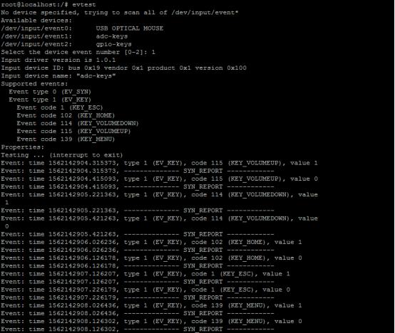
evtest
  Select test equipment
Select the device event number [0-2]: 1
Enter the serial number corresponding to "adc-keys", here is 1

  Press the button on the development board
Press "Ctrl" + "C" on the computer to end the key test program.
RTC Test
test introduction
Affected by express shipping, the MYZR-RK3399-EK314 series evaluation board is shipped without batteries. Please prepare your own coin-cell battery and install it on the evaluation board before testing the RTC. The battery holder of MYZR-RK3399-EK314 is in the "BT1" position on the back of the bottom plate.
Test operation
1. Power off and restart the device to view the current system time and hardware time:
=====> Input:
date

=====> Output:
Thu Aug 6 05:35:17 UTC 2012
2. View the current RTC chip clock:
=====> Input:
hwclock

=====> Output:
Thu Aug 6 05:35:59 2012 0.000000 seconds
3. Set the system clock and synchronize to the RTC chip
=====> Input:
date -s "2019-07-04 12:30:30"
4. Write system clock to hardware clock
=====> Input:
hwclock -w
Test Results
The clock you see after step 3 is the newly set clock.
Audio playback test
test introduction
This test verifies the audio capabilities of the evaluation board by playing audio files.
- Test operation **
- Test operation **
Connect the audio output device to the audio socket on the front of the baseboard. The audio socket is on the front of the baseboard. "P6".
Execute the test command:
=====> Input:
#aplay /usr/share/sounds/alsa/Rear_Left.wav
Test Results
Part III Display Function Test
test introduction
Connect the EDP display.
Test Methods
   Flash boot_edp.img

   Flash with AndroidTool_Release_v2.58.
Test Results
Power on, EDP display image
Part IV Demonstration of Expansion Module Functions
WIFI module test
The model of WIFI chip used by MYZR-RK3399-EK314 evaluation board is AP6354
Test operation
   1. Click on the network settings icon in the upper right corner of the screen and a list of networks will pop up

   2. Select the wifi you want to connect and click

   3. Enter the wifi password in the pop-up window and click Connect
Bluetooth module test
The model of Bluetooth chip used by MYZR-RK3399-EK314 evaluation board is AP6354
Test operation
  1. Click the Bluetooth icon in the upper right corner of the screen, and then click the Devices option in the pop-up list.
  2. Click “Search” in the pop-up window to start searching for Bluetooth.
4G Module Test
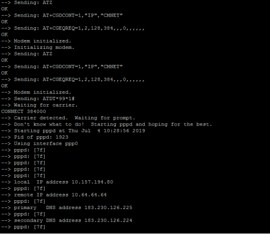
Test the internet 4G module, such as L506.
Test operation
     Install wvdial
=====> Input:
sudo apt-get install wvdial

Modify the configuration file /etc/wvdial.conf
=====> Input:
# vim /etc/wvdial.conf

    Add the following:
[Dialer Defaults]
Modem = /dev/ttyUSB2
Baud = 115200
Init1 = ATZ
Init2 = AT+CGDCONT=1,"IP","CMNET"
Init3 = AT+CGEQREQ=1,2,128,384,,,0,,,,,,
Phone = *99*1#
Username = cmnet
Password = cmnet
New PPPD = yes
=====> Input:
#wvdial &
--------------------------------------------------------------------------------
* 珠海明远智睿科技有限公司
* ZhuHai MYZR Technology CO.,LTD.
* Latest Update: 2019/02/19
* Supporter: Tang Bin
--------------------------------------------------------------------------------


