“MYZR-SAMA5-MB200 硬件介绍”的版本间的差异
| 第1行: | 第1行: | ||
| − | = '''MY-SAMA5-EK200视图''' = | + | = '''MY-SAMA5-EK200视图(MY-SAMA5-EK200 view)''' = |
---- | ---- | ||
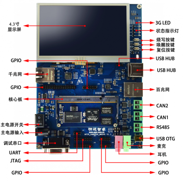
| − | == '''正面视图''' == | + | == '''正面视图(top view)''' == |
[[文件:MY-SAMA5-MB200_1.1.0.1.png|642px]]<br> | [[文件:MY-SAMA5-MB200_1.1.0.1.png|642px]]<br> | ||
| − | == '''背面视图''' == | + | |
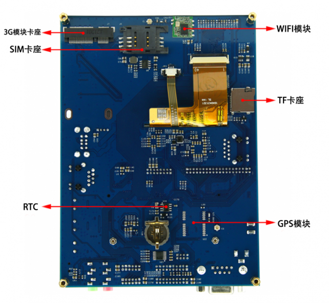
| + | == '''背面视图(bottom view)''' == | ||
[[文件:MY-SAMA5-MB200_1.2.0.1.png|642px]]<br> | [[文件:MY-SAMA5-MB200_1.2.0.1.png|642px]]<br> | ||
| − | = '''接口描述''' = | + | = '''接口描述(description of interfaces)''' = |
---- | ---- | ||
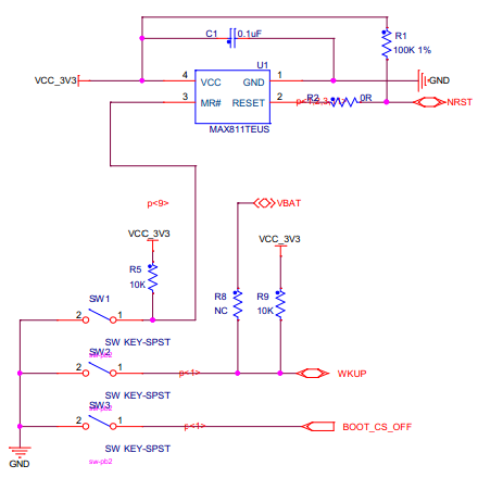
| − | == '''按键''' == | + | == '''按键(key)''' == |
{| class="wikitable" | {| class="wikitable" | ||
|- | |- | ||
| − | ! | + | !丝印<br>(silkscreen) |
| − | !信号 | + | !信号<br>(signal) |
| − | !功能 | + | !功能<br>(function) |
| − | !描述 | + | !描述<br>(description) |
|- | |- | ||
|SW1 | |SW1 | ||
|NRST | |NRST | ||
| − | |设备复位 | + | |设备复位<br>(device reset) |
| − | |按下设备复位 | + | |按下设备复位<br>(press device reset) |
|- | |- | ||
|SW2 | |SW2 | ||
|WKUP | |WKUP | ||
| − | |唤醒 | + | |唤醒<br>(wake up) |
| − | |按下产生唤醒信号 | + | |按下产生唤醒信号<br>(boot mode contrl) |
|- | |- | ||
|SW3 | |SW3 | ||
|BOOT_CS_OFF | |BOOT_CS_OFF | ||
| − | |启动模式控制 | + | |启动模式控制<br>(boot mode contrl) |
| − | |按下并上电,设备进入下载模式 | + | |按下并上电,设备进入下载模式<br>(press to generate wake up signal) |
|} | |} | ||
[[文件:MY-SAMA5-MB200_2.1.0.1.png|642px]]<br> | [[文件:MY-SAMA5-MB200_2.1.0.1.png|642px]]<br> | ||
| − | == '''USB下载口''' == | + | |
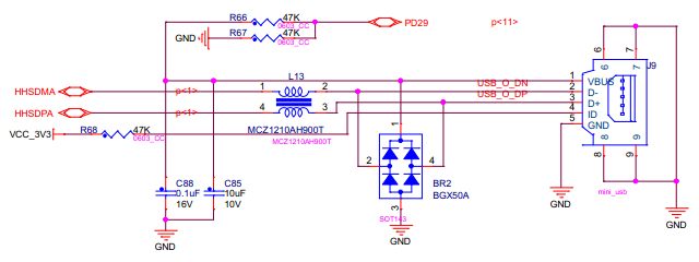
| + | == '''USB下载口(USB download port)''' == | ||
{| class="wikitable" | {| class="wikitable" | ||
|- | |- | ||
| − | ! | + | !丝印<br>(silkscreen) |
| − | !信号 | + | !信号<br>(signal) |
| − | !功能 | + | !功能<br>(function) |
| − | !描述 | + | !描述<br>(description) |
|- | |- | ||
|J9 | |J9 | ||
|HHSDMA,HHSDPA | |HHSDMA,HHSDPA | ||
| − | |烧录接口 | + | |烧录接口<br>(programming interface) |
| − | |设备进入下载模式后,通过此接口烧录程序 | + | |设备进入下载模式后,通过此接口烧录程序<br>(after device is entered into mode of download,programming will be done via this interface) |
|} | |} | ||
[[文件:MY-SAMA5-MB200_2.2.0.1.png|642px]]<br> | [[文件:MY-SAMA5-MB200_2.2.0.1.png|642px]]<br> | ||
| − | == '''USB接口''' == | + | |
| + | == '''USB接口(USB interface)''' == | ||
=== USB-B & USB3 === | === USB-B & USB3 === | ||
{| class="wikitable" | {| class="wikitable" | ||
|- | |- | ||
| − | ! | + | !丝印<br>(silkscreen) |
| − | !信号 | + | !信号<br>(signal) |
| − | !功能 | + | !功能<br>(function) |
| − | !描述 | + | !描述<br>(description) |
|- | |- | ||
|U10 | |U10 | ||
|HHSDPB,HHSDMB | |HHSDPB,HHSDMB | ||
| − | |USB HUB芯片 | + | |USB HUB芯片<br>(USB HUB chip) |
| − | |通过USB2514扩展出3个USB接口和一个3G USB接口 | + | |通过USB2514扩展出3个USB接口和一个3G USB接口<br>(USB2514 is expanded to 3 USB ports and 1 3G USB port) |
|- | |- | ||
|J11 | |J11 | ||
|USBDN_DP3,USBDN_DM3 | |USBDN_DP3,USBDN_DM3 | ||
|USB | |USB | ||
| − | |USB插座接口 | + | |USB插座接口<br>(USB socket port) |
|} | |} | ||
[[文件:MY-SAMA5-MB200_2.3.1.1.png|642px]]<br> | [[文件:MY-SAMA5-MB200_2.3.1.1.png|642px]]<br> | ||
| + | |||
=== USB1 & USB2 === | === USB1 & USB2 === | ||
{| class="wikitable" | {| class="wikitable" | ||
|- | |- | ||
| − | ! | + | !丝印<br>(silkscreen) |
| − | !信号 | + | !信号<br>(signal) |
| − | !功能 | + | !功能<br>(function) |
| − | !描述 | + | !描述<br>(description) |
|- | |- | ||
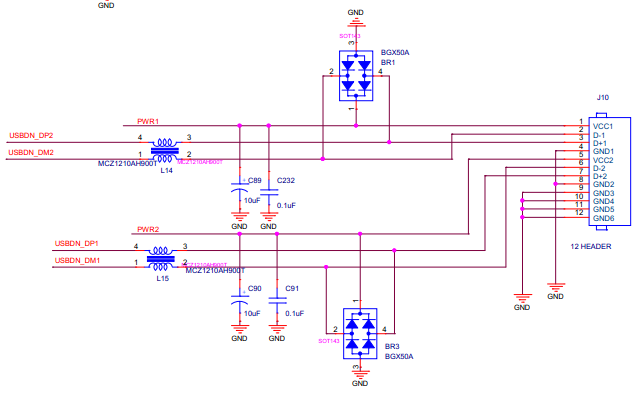
|J10[1~4] | |J10[1~4] | ||
|USBDN_DP2,USBDN_DM2 | |USBDN_DP2,USBDN_DM2 | ||
|USB | |USB | ||
| − | |USB接口 | + | |USB接口<br>(USB port) |
|- | |- | ||
|J10[5~8] | |J10[5~8] | ||
|USBDN_DP1,USBDN_DM1 | |USBDN_DP1,USBDN_DM1 | ||
|USB | |USB | ||
| − | |USB接口 | + | |USB接口<br>(USB port) |
|} | |} | ||
[[文件:MY-SAMA5-MB200_2.3.2.1.png|642px]]<br> | [[文件:MY-SAMA5-MB200_2.3.2.1.png|642px]]<br> | ||
| − | === USB WIFI模块 === | + | |
| + | === USB WIFI模块(USB WIFI module) === | ||
{| class="wikitable" | {| class="wikitable" | ||
|- | |- | ||
| − | ! | + | !丝印<br>(silkscreen) |
| − | !信号 | + | !信号<br>(signal) |
| − | !功能 | + | !功能<br>(function) |
| − | !描述 | + | !描述<br>(description) |
|- | |- | ||
|U11 | |U11 | ||
|HHSDPC,HHSDMC | |HHSDPC,HHSDMC | ||
|USB-WIFI | |USB-WIFI | ||
| − | |使用USB-C用作USB-WIFI(RTL8188EUS)接口 | + | |使用USB-C用作USB-WIFI(RTL8188EUS)接口<br>(USB-C is used as USB-WIFI(RTL8188EUS) interface) |
|} | |} | ||
[[文件:MY-SAMA5-MB200_2.3.3.1.png|642px]]<br> | [[文件:MY-SAMA5-MB200_2.3.3.1.png|642px]]<br> | ||
| − | == '''LCD、背光及触摸屏''' == | + | |
| + | == '''LCD、背光及触摸屏(LCD、backlight and touch screen)''' == | ||
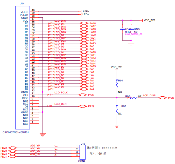
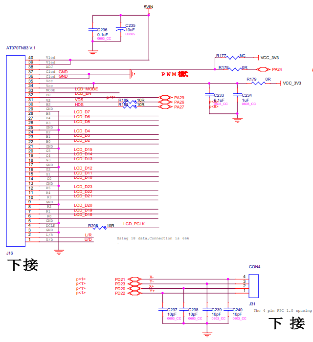
LCD有2组接口,2组接口共用一组信号。其中一组支持24位,另一组支持18位(使用24数据位可以兼容这2组接口)。<br> | LCD有2组接口,2组接口共用一组信号。其中一组支持24位,另一组支持18位(使用24数据位可以兼容这2组接口)。<br> | ||
| − | === 24位LCD显示及触摸屏接口 === | + | <span style="background:#CCCCCC">LCD has two groups of interfaces,these two groups of interfaces share the same group of signal。one group support 24bit,another group support 18bit(24 data bit can be compatible to these two groups of interfaces)</span><br> |
| + | |||
| + | === 24位LCD显示及触摸屏接口(24bit LCD display and touch screen interface) === | ||
{| class="wikitable" | {| class="wikitable" | ||
|- | |- | ||
| − | ! | + | !丝印<br>(silkscreen) |
| − | !信号 | + | !信号<br>(signal) |
| − | !功能 | + | !功能<br>(function) |
| − | !描述 | + | !描述<br>(description) |
|- | |- | ||
|J14 | |J14 | ||
|PA* | |PA* | ||
| − | |LCD接口 | + | |LCD接口<br>(LCD interface) |
| − | |24位LCD显示屏接口 | + | |24位LCD显示屏接口<br>(24bit LCD display touch screen interface) |
|- | |- | ||
|J15 | |J15 | ||
|PD20~PD23 | |PD20~PD23 | ||
| − | |触摸屏接口 | + | |触摸屏接口<br>(touch screen interface) |
| − | |4线电阻触摸屏接口 | + | |4线电阻触摸屏接口<br>(4thread resistance touch screen interface) |
|} | |} | ||
[[文件:MY-SAMA5-MB200_2.4.1.1.png|642px]]<br> | [[文件:MY-SAMA5-MB200_2.4.1.1.png|642px]]<br> | ||
| − | === 18位LCD触摸屏接口 === | + | |
| + | === 18位LCD触摸屏接口(18bit LCD touch screen interface) === | ||
{| class="wikitable" | {| class="wikitable" | ||
|- | |- | ||
| − | ! | + | !丝印<br>(silkscreen) |
| − | !信号 | + | !信号<br>(signal) |
| − | !功能 | + | !功能<br>(function) |
| − | !描述 | + | !描述<br>(description) |
|- | |- | ||
|J16 | |J16 | ||
|PA* | |PA* | ||
| − | |LCD接口 | + | |LCD接口<br>(LCD interface) |
| − | |18位LCD显示屏接口 | + | |18位LCD显示屏接口<br>(18bit LCD display screen interface) |
|- | |- | ||
|J31 | |J31 | ||
|PD20~PD23 | |PD20~PD23 | ||
| − | |触摸屏接口 | + | |触摸屏接口<br>(touch screen interface) |
| − | |4线电阻触摸屏接口 | + | |4线电阻触摸屏接口<br>(18bit LCD display screen interface) |
|} | |} | ||
[[文件:MY-SAMA5-MB200_2.4.2.1.png|642px]]<br> | [[文件:MY-SAMA5-MB200_2.4.2.1.png|642px]]<br> | ||
| − | === 背光控制 === | + | |
| + | === 背光控制(backlight control) === | ||
{| class="wikitable" | {| class="wikitable" | ||
|- | |- | ||
| − | ! | + | !丝印<br>(silkscreen) |
| − | !信号 | + | !信号<br>(signal) |
| − | !功能 | + | !功能<br>(function) |
| − | !描述 | + | !描述<br>(description) |
|- | |- | ||
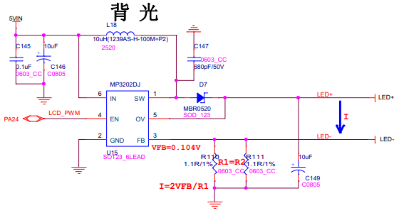
|MP3202DJ | |MP3202DJ | ||
|PA24(LCD_PWM) | |PA24(LCD_PWM) | ||
| − | |LCD背光调节 | + | |LCD背光调节<br>(LCD backlight regulation) |
| − | |LCD背光亮度调节 | + | |LCD背光亮度调节<br>(regulation of LCD backlight brighteness) |
|} | |} | ||
[[文件:MY-SAMA5-MB200_2.4.3.1.png|642px]]<br> | [[文件:MY-SAMA5-MB200_2.4.3.1.png|642px]]<br> | ||
| − | == '''LED接口''' == | + | |
| + | == '''LED接口(LED interface)''' == | ||
{| class="wikitable" | {| class="wikitable" | ||
|- | |- | ||
| − | ! | + | !丝印<br>(silkscreen) |
| − | !信号 | + | !信号<br>(signal) |
| − | !功能 | + | !功能<br>(function) |
| − | !描述 | + | !描述<br>(description) |
|- | |- | ||
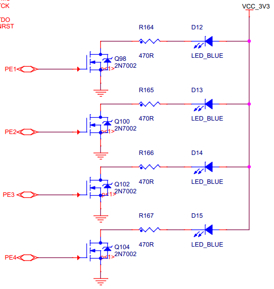
|D12 | |D12 | ||
|PE1 | |PE1 | ||
|GPIO-LED | |GPIO-LED | ||
| − | |实现为内核启动后该LED常亮 | + | |实现为内核启动后该LED常亮<br>(the LED is realized to solid lit after kernel booting) |
|- | |- | ||
|D13 | |D13 | ||
|PE2 | |PE2 | ||
|GPIO-LED | |GPIO-LED | ||
| − | |实现为CPU正常工作时LED闪烁 | + | |实现为CPU正常工作时LED闪烁<br>(LED is realized to flash when CPU is working normally) |
|- | |- | ||
|D14 | |D14 | ||
|PE3 | |PE3 | ||
|GPIO-LED | |GPIO-LED | ||
| − | |实现为通用GPIO-LED,系统下用户可控制LED亮灭 | + | |实现为通用GPIO-LED,系统下用户可控制LED亮灭<br>(it is realized to be as universial GPIO-LED,users can control on/off of the LED in the system) |
|- | |- | ||
|D15 | |D15 | ||
|PE4 | |PE4 | ||
|GPIO-LED | |GPIO-LED | ||
| − | |实现为GPIO-TIMER,系统下可调节高低电平持续时间 | + | |实现为GPIO-TIMER,系统下可调节高低电平持续时间<br>(it is realized as GPIO-TIMER,which can regulate holding time of high/low electrical level in the system) |
|} | |} | ||
说明:LED复用EBI的4个引脚(即如果要使用EBI,则不能实现PE1~PE4为LED)。<br> | 说明:LED复用EBI的4个引脚(即如果要使用EBI,则不能实现PE1~PE4为LED)。<br> | ||
| + | <span style="background:#CCCCCC">instruction:LED multiplex the 4 pins of EBI(e.g if want to use EBI,then PE1~PE4 can't work sa LED)</span><br> | ||
[[文件:MY-SAMA5-MB200_2.5.0.1.png|642px]]<br> | [[文件:MY-SAMA5-MB200_2.5.0.1.png|642px]]<br> | ||
| − | == '''串口''' == | + | |
| − | === 调试串口 === | + | == '''串口(serial port)''' == |
| + | === 调试串口(debug serial port) === | ||
{| class="wikitable" | {| class="wikitable" | ||
|- | |- | ||
| − | ! | + | !丝印<br>(silkscreen) |
| − | !信号 | + | !信号<br>(signal) |
| − | !功能 | + | !功能<br>(function) |
| − | !描述 | + | !描述<br>(description) |
|- | |- | ||
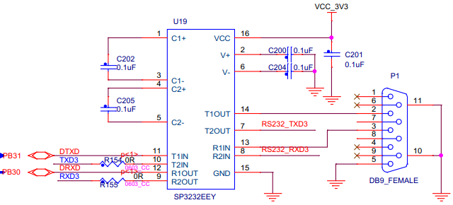
|P1 | |P1 | ||
|DTXD,DRXD | |DTXD,DRXD | ||
| − | |调试串口 | + | |调试串口<br>(debug serial port) |
| − | |用于系统信息输出,系统控制命令输入。 | + | |用于系统信息输出,系统控制命令输入。<br>(to be used as output of system information and input of system control command) |
|} | |} | ||
[[文件:MY-SAMA5-MB200_2.6.1.1.png|642px]]<br> | [[文件:MY-SAMA5-MB200_2.6.1.1.png|642px]]<br> | ||
| + | |||
=== USART&UART === | === USART&UART === | ||
{| class="wikitable" | {| class="wikitable" | ||
|- | |- | ||
| − | ! | + | !丝印<br>(silkscreen) |
| − | !信号 | + | !信号<br>(signal) |
| − | !功能 | + | !功能<br>(function) |
| − | !描述 | + | !描述<br>(description) |
|- | |- | ||
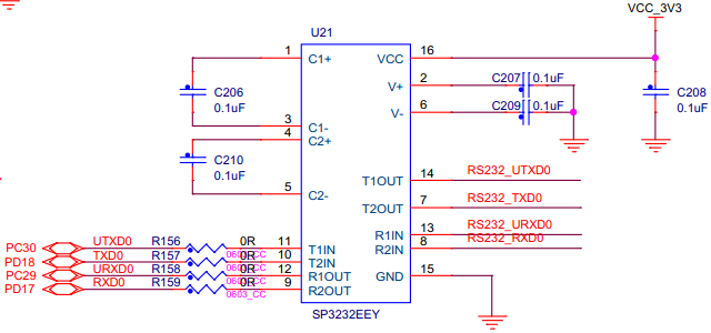
|U21(9,10) | |U21(9,10) | ||
|TXD0,RXD0 | |TXD0,RXD0 | ||
|USART0 | |USART0 | ||
| − | |USART0信号<br> | + | |USART0信号<br>(USART0 signal) |
|- | |- | ||
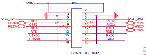
|J26(11~14) | |J26(11~14) | ||
|TXD1,RTS1,CTS1,RXD1 | |TXD1,RTS1,CTS1,RXD1 | ||
|USART1 | |USART1 | ||
| − | |USART插针接口<br> | + | |USART插针接口<br>(USART pin interface) |
|- | |- | ||
|J26(7~10) | |J26(7~10) | ||
|TXD2,RTS2,CTS2,RXD2 | |TXD2,RTS2,CTS2,RXD2 | ||
|USART2 | |USART2 | ||
| − | |USART插针接口<br> | + | |USART插针接口<br>(USART pin interface) |
|- | |- | ||
|J26(16,18) | |J26(16,18) | ||
|RXD3,TXD3 | |RXD3,TXD3 | ||
|USART3 | |USART3 | ||
| − | |USART插针接口<br> | + | |USART插针接口<br>(USART pin interface) |
|- | |- | ||
|J26(15,17) | |J26(15,17) | ||
|UTXD0,URXD0 | |UTXD0,URXD0 | ||
|UART0 | |UART0 | ||
| − | |UART插针接口<br> | + | |UART插针接口<br>(USART pin interface) |
|} | |} | ||
[[文件:MY-SAMA5-MB200_2.6.2.1.png|642px]]<br> | [[文件:MY-SAMA5-MB200_2.6.2.1.png|642px]]<br> | ||
| 第237行: | 第251行: | ||
<br> | <br> | ||
[[文件:MY-SAMA5-MB200_2.6.2.2.png|642px]]<br> | [[文件:MY-SAMA5-MB200_2.6.2.2.png|642px]]<br> | ||
| + | |||
=== RS232 === | === RS232 === | ||
{| class="wikitable" | {| class="wikitable" | ||
|- | |- | ||
| − | ! | + | !丝印<br>(silkscreen) |
| − | !信号 | + | !信号<br>(signal) |
| − | !功能 | + | !功能<br>(function) |
| − | !描述 | + | !描述<br>(description) |
|- | |- | ||
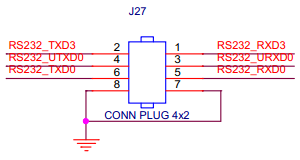
|J27(1,2) | |J27(1,2) | ||
|RS232_RXD3, RS232_TXD3 | |RS232_RXD3, RS232_TXD3 | ||
|RS232 | |RS232 | ||
| − | |USART3复用为RS232<br> | + | |USART3复用为RS232<br>(USART3 is multiplexed as RS232) |
|- | |- | ||
|J27(3,4) | |J27(3,4) | ||
|RS232_URXD0, RS232_UTXD0 | |RS232_URXD0, RS232_UTXD0 | ||
|RS232 | |RS232 | ||
| − | |UART0复用为RS232<br> | + | |UART0复用为RS232<br>(UART0 is multiplexed as RS232) |
|- | |- | ||
|J27(5,6) | |J27(5,6) | ||
|RS232_TXD0, RS232_RXD0 | |RS232_TXD0, RS232_RXD0 | ||
|RS232 | |RS232 | ||
| − | |USART0复用为RS232<br> | + | |USART0复用为RS232<br>(UART0 is multiplexed as RS232) |
|} | |} | ||
[[文件:MY-SAMA5-MB200_2.6.3.1.png|642px]]<br> | [[文件:MY-SAMA5-MB200_2.6.3.1.png|642px]]<br> | ||
| + | |||
=== RS485 === | === RS485 === | ||
{| class="wikitable" | {| class="wikitable" | ||
|- | |- | ||
| − | ! | + | !丝印<br>(silkscreen) |
| − | !信号 | + | !信号<br>(signal) |
| − | !功能 | + | !功能<br>(function) |
| − | !描述 | + | !描述<br>(description) |
|- | |- | ||
|J25 | |J25 | ||
|RS485_2_RX-,RS485_2_TX- | |RS485_2_RX-,RS485_2_TX- | ||
|RS485 | |RS485 | ||
| − | |USART1复用为RS485<br> | + | |USART1复用为RS485<br>(USART1 is multiplexed as RS485) |
|} | |} | ||
[[文件:MY-SAMA5-MB200_2.6.4.1.png|642px]]<br> | [[文件:MY-SAMA5-MB200_2.6.4.1.png|642px]]<br> | ||
| − | == '''EBI''' == | + | |
| + | == '''EBI()''' == | ||
{| class="wikitable" | {| class="wikitable" | ||
|- | |- | ||
| − | ! | + | !丝印<br>(silkscreen) |
| − | !信号 | + | !信号<br>(signal) |
| − | !功能 | + | !功能<br>(function) |
| − | !描述 | + | !描述<br>(description) |
|- | |- | ||
| − | |rowspan=2|J23 | + | |rowspan=2|J23 |
|D0~D7 | |D0~D7 | ||
| − | |EBI数据线 | + | |EBI数据线<br>(EBI data line) |
| − | |rowspan=2|外部总线接口<br> | + | |rowspan=2|外部总线接口<br>(infterface of external bus) |
|- | |- | ||
|PE0~PE20 | |PE0~PE20 | ||
| − | |EBI地址线 | + | |EBI地址线<br>(EBI address line) |
|} | |} | ||
说明:EBI的PE1~PE4实现为LED,如果要使用EBI,需要重新配置PE1~PE4。<br> | 说明:EBI的PE1~PE4实现为LED,如果要使用EBI,需要重新配置PE1~PE4。<br> | ||
| + | <span style="background:#CCCCCC">instruction:EBI的PE1~PE4 are realized as LED,if want to use EBI,need to reconfigure PE1~PE4。</span><br> | ||
[[文件:MY-SAMA5-MB200_2.7.0.1.png|642px]]<br> | [[文件:MY-SAMA5-MB200_2.7.0.1.png|642px]]<br> | ||
| − | == '''千兆以太网''' == | + | |
| + | == '''千兆以太网(Gbps ethernet)''' == | ||
接口丝印:J2。芯片丝印:U2。芯片型号:KSZ9031RN。<br> | 接口丝印:J2。芯片丝印:U2。芯片型号:KSZ9031RN。<br> | ||
| + | <span style="background:#CCCCCC">silkscreen of interface:J2。silkscreen of chip:U2。chip model:KSZ9031RN</span><br> | ||
[[文件:MY-SAMA5-MB200_2.8.0.1.png|642px]]<br> | [[文件:MY-SAMA5-MB200_2.8.0.1.png|642px]]<br> | ||
| − | == '''百兆以太网''' == | + | |
| + | == '''百兆以太网(Mbps ethernet)''' == | ||
接口丝印:J3。芯片丝印:U4。芯片型号:KSZ8081RNB。<br> | 接口丝印:J3。芯片丝印:U4。芯片型号:KSZ8081RNB。<br> | ||
| + | <span style="background:#CCCCCC">silkscreen of interface:J3。silkscreen of chip:U4。chip model:KSZ8081RNB</span><br> | ||
[[文件:MY-SAMA5-MB200_2.9.0.1.png|642px]]<br> | [[文件:MY-SAMA5-MB200_2.9.0.1.png|642px]]<br> | ||
| − | == '''SD接口''' == | + | |
| + | == '''SD接口(SD port)''' == | ||
接口丝印:U23。<br> | 接口丝印:U23。<br> | ||
| + | <span style="background:#CCCCCC">silkscreen of interface: U23</span><br> | ||
[[文件:MY-SAMA5-MB200_2.10.0.1.png|642px]]<br> | [[文件:MY-SAMA5-MB200_2.10.0.1.png|642px]]<br> | ||
| − | == '''CAN0接口''' == | + | |
| + | == '''CAN0接口(CAN0 interface)''' == | ||
接口丝印:U12。<br> | 接口丝印:U12。<br> | ||
| + | <span style="background:#CCCCCC">silkscreen of interface: U12</span><br> | ||
[[文件:MY-SAMA5-MB200_2.11.0.1.png|642px]]<br> | [[文件:MY-SAMA5-MB200_2.11.0.1.png|642px]]<br> | ||
| − | == '''CAN1接口''' == | + | |
| + | == '''CAN1接口(CAN1 interface)''' == | ||
接口丝印:U13。<br> | 接口丝印:U13。<br> | ||
| + | <span style="background:#CCCCCC">silkscreen of interface: U13</span><br> | ||
[[文件:MY-SAMA5-MB200_2.12.0.1.png|642px]]<br> | [[文件:MY-SAMA5-MB200_2.12.0.1.png|642px]]<br> | ||
| + | |||
== '''RTC''' == | == '''RTC''' == | ||
使用外部RTC。芯片丝印:U13。芯片型号:ISL1208<br> | 使用外部RTC。芯片丝印:U13。芯片型号:ISL1208<br> | ||
| + | <span style="background:#CCCCCC">use external RTC。silkscreen of chip:U13。chip model:ISL1208</span><br> | ||
[[文件:MY-SAMA5-MB200_2.13.0.1.png|642px]]<br> | [[文件:MY-SAMA5-MB200_2.13.0.1.png|642px]]<br> | ||
| − | == '''音频(WM8904)''' == | + | |
| + | == '''音频(WM8904)(audio(WM8904))''' == | ||
[[文件:MY-SAMA5-MB200_2.14.0.1.png|642px]]<br> | [[文件:MY-SAMA5-MB200_2.14.0.1.png|642px]]<br> | ||
| + | |||
== '''PCI-E''' == | == '''PCI-E''' == | ||
PCI-E接口丝印:J7。SIM卡接口丝印:J6<br> | PCI-E接口丝印:J7。SIM卡接口丝印:J6<br> | ||
| + | <span style="background:#CCCCCC">silkscreen of PCI-E: J7.silkscreen of SIM card:J6</span><br> | ||
[[文件:MY-SAMA5-MB200_2.15.0.1.png|642px]]<br> | [[文件:MY-SAMA5-MB200_2.15.0.1.png|642px]]<br> | ||
| + | |||
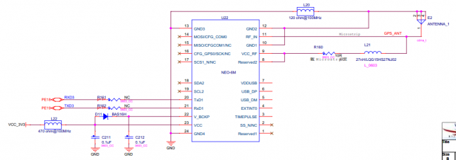
== '''GPS''' == | == '''GPS''' == | ||
芯片丝印:U22。模块型号:NEO-6M<br> | 芯片丝印:U22。模块型号:NEO-6M<br> | ||
| + | <span style="background:#CCCCCC">silkscreen of chip: U22. module model:NEO-6M</span><br> | ||
[[文件:MY-SAMA5-MB200_2.16.0.1.png|642px]]<br> | [[文件:MY-SAMA5-MB200_2.16.0.1.png|642px]]<br> | ||
| + | |||
== '''JTAG''' == | == '''JTAG''' == | ||
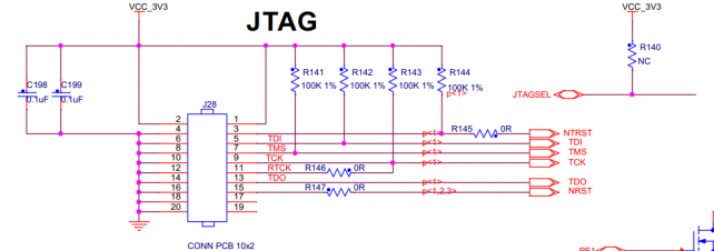
接口丝印:J28<br> | 接口丝印:J28<br> | ||
| + | <span style="background:#CCCCCC">silkscreen of interface: J28</span><br> | ||
[[文件:MY-SAMA5-MB200_2.17.0.1.png|642px]]<br> | [[文件:MY-SAMA5-MB200_2.17.0.1.png|642px]]<br> | ||
2017年6月26日 (一) 11:55的版本
目录
- 1 = MY-SAMA5-EK200视图(MY-SAMA5-EK200 view) =
- 2 正面视图(top view)
- 3 背面视图(bottom view)
- 4 = 接口描述(description of interfaces) =
- 5 按键(key)
- 6 USB下载口(USB download port)
- 7 USB接口(USB interface)
- 8 LCD、背光及触摸屏(LCD、backlight and touch screen)
- 9 LED接口(LED interface)
- 10 串口(serial port)
- 11 EBI()
- 12 千兆以太网(Gbps ethernet)
- 13 百兆以太网(Mbps ethernet)
- 14 SD接口(SD port)
- 15 CAN0接口(CAN0 interface)
- 16 CAN1接口(CAN1 interface)
- 17 RTC
- 18 音频(WM8904)(audio(WM8904))
- 19 PCI-E
- 20 GPS
- 21 JTAG
= MY-SAMA5-EK200视图(MY-SAMA5-EK200 view) =
正面视图(top view)
背面视图(bottom view)
= 接口描述(description of interfaces) =
按键(key)
| 丝印 (silkscreen) |
信号 (signal) |
功能 (function) |
描述 (description) |
|---|---|---|---|
| SW1 |
NRST |
设备复位 (device reset) |
按下设备复位 (press device reset) |
| SW2 |
WKUP |
唤醒 (wake up) |
按下产生唤醒信号 (boot mode contrl) |
| SW3 |
BOOT_CS_OFF |
启动模式控制 (boot mode contrl) |
按下并上电,设备进入下载模式 (press to generate wake up signal) |
USB下载口(USB download port)
| 丝印 (silkscreen) |
信号 (signal) |
功能 (function) |
描述 (description) |
|---|---|---|---|
| J9 | HHSDMA,HHSDPA |
烧录接口 (programming interface) |
设备进入下载模式后,通过此接口烧录程序 (after device is entered into mode of download,programming will be done via this interface) |
USB接口(USB interface)
USB-B & USB3
| 丝印 (silkscreen) |
信号 (signal) |
功能 (function) |
描述 (description) |
|---|---|---|---|
| U10 |
HHSDPB,HHSDMB |
USB HUB芯片 (USB HUB chip) |
通过USB2514扩展出3个USB接口和一个3G USB接口 (USB2514 is expanded to 3 USB ports and 1 3G USB port) |
| J11 |
USBDN_DP3,USBDN_DM3 |
USB |
USB插座接口 (USB socket port) |
USB1 & USB2
| 丝印 (silkscreen) |
信号 (signal) |
功能 (function) |
描述 (description) |
|---|---|---|---|
| J10[1~4] |
USBDN_DP2,USBDN_DM2 |
USB |
USB接口 (USB port) |
| J10[5~8] |
USBDN_DP1,USBDN_DM1 |
USB |
USB接口 (USB port) |
USB WIFI模块(USB WIFI module)
| 丝印 (silkscreen) |
信号 (signal) |
功能 (function) |
描述 (description) |
|---|---|---|---|
| U11 |
HHSDPC,HHSDMC |
USB-WIFI |
使用USB-C用作USB-WIFI(RTL8188EUS)接口 (USB-C is used as USB-WIFI(RTL8188EUS) interface) |
LCD、背光及触摸屏(LCD、backlight and touch screen)
LCD有2组接口,2组接口共用一组信号。其中一组支持24位,另一组支持18位(使用24数据位可以兼容这2组接口)。
LCD has two groups of interfaces,these two groups of interfaces share the same group of signal。one group support 24bit,another group support 18bit(24 data bit can be compatible to these two groups of interfaces)
24位LCD显示及触摸屏接口(24bit LCD display and touch screen interface)
| 丝印 (silkscreen) |
信号 (signal) |
功能 (function) |
描述 (description) |
|---|---|---|---|
| J14 |
PA* |
LCD接口 (LCD interface) |
24位LCD显示屏接口 (24bit LCD display touch screen interface) |
| J15 |
PD20~PD23 |
触摸屏接口 (touch screen interface) |
4线电阻触摸屏接口 (4thread resistance touch screen interface) |
18位LCD触摸屏接口(18bit LCD touch screen interface)
| 丝印 (silkscreen) |
信号 (signal) |
功能 (function) |
描述 (description) |
|---|---|---|---|
| J16 |
PA* |
LCD接口 (LCD interface) |
18位LCD显示屏接口 (18bit LCD display screen interface) |
| J31 |
PD20~PD23 |
触摸屏接口 (touch screen interface) |
4线电阻触摸屏接口 (18bit LCD display screen interface) |
背光控制(backlight control)
| 丝印 (silkscreen) |
信号 (signal) |
功能 (function) |
描述 (description) |
|---|---|---|---|
| MP3202DJ |
PA24(LCD_PWM) |
LCD背光调节 (LCD backlight regulation) |
LCD背光亮度调节 (regulation of LCD backlight brighteness) |
LED接口(LED interface)
| 丝印 (silkscreen) |
信号 (signal) |
功能 (function) |
描述 (description) |
|---|---|---|---|
| D12 |
PE1 |
GPIO-LED |
实现为内核启动后该LED常亮 (the LED is realized to solid lit after kernel booting) |
| D13 |
PE2 |
GPIO-LED |
实现为CPU正常工作时LED闪烁 (LED is realized to flash when CPU is working normally) |
| D14 |
PE3 |
GPIO-LED |
实现为通用GPIO-LED,系统下用户可控制LED亮灭 (it is realized to be as universial GPIO-LED,users can control on/off of the LED in the system) |
| D15 |
PE4 |
GPIO-LED |
实现为GPIO-TIMER,系统下可调节高低电平持续时间 (it is realized as GPIO-TIMER,which can regulate holding time of high/low electrical level in the system) |
说明:LED复用EBI的4个引脚(即如果要使用EBI,则不能实现PE1~PE4为LED)。
instruction:LED multiplex the 4 pins of EBI(e.g if want to use EBI,then PE1~PE4 can't work sa LED)
串口(serial port)
调试串口(debug serial port)
| 丝印 (silkscreen) |
信号 (signal) |
功能 (function) |
描述 (description) |
|---|---|---|---|
| P1 | DTXD,DRXD |
调试串口 (debug serial port) |
用于系统信息输出,系统控制命令输入。 (to be used as output of system information and input of system control command) |
USART&UART
| 丝印 (silkscreen) |
信号 (signal) |
功能 (function) |
描述 (description) |
|---|---|---|---|
| U21(9,10) |
TXD0,RXD0 |
USART0 | USART0信号 (USART0 signal) |
| J26(11~14) | TXD1,RTS1,CTS1,RXD1 |
USART1 | USART插针接口 (USART pin interface) |
| J26(7~10) |
TXD2,RTS2,CTS2,RXD2 |
USART2 | USART插针接口 (USART pin interface) |
| J26(16,18) | RXD3,TXD3 |
USART3 | USART插针接口 (USART pin interface) |
| J26(15,17) | UTXD0,URXD0 |
UART0 |
UART插针接口 (USART pin interface) |
RS232
| 丝印 (silkscreen) |
信号 (signal) |
功能 (function) |
描述 (description) |
|---|---|---|---|
| J27(1,2) |
RS232_RXD3, RS232_TXD3 | RS232 |
USART3复用为RS232 (USART3 is multiplexed as RS232) |
| J27(3,4) |
RS232_URXD0, RS232_UTXD0 |
RS232 |
UART0复用为RS232 (UART0 is multiplexed as RS232) |
| J27(5,6) |
RS232_TXD0, RS232_RXD0 | RS232 |
USART0复用为RS232 (UART0 is multiplexed as RS232) |
RS485
| 丝印 (silkscreen) |
信号 (signal) |
功能 (function) |
描述 (description) |
|---|---|---|---|
| J25 |
RS485_2_RX-,RS485_2_TX- |
RS485 |
USART1复用为RS485 (USART1 is multiplexed as RS485) |
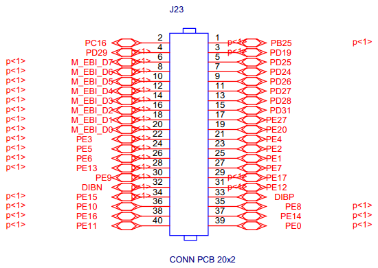
EBI()
| 丝印 (silkscreen) |
信号 (signal) |
功能 (function) |
描述 (description) | |||||
|---|---|---|---|---|---|---|---|---|
| J23 |
D0~D7 |
EBI数据线 (EBI data line)
|
PE0~PE20 |
EBI地址线 (EBI address line) |
说明:EBI的PE1~PE4实现为LED,如果要使用EBI,需要重新配置PE1~PE4。
instruction:EBI的PE1~PE4 are realized as LED,if want to use EBI,need to reconfigure PE1~PE4。
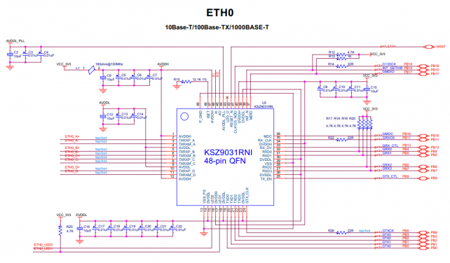
千兆以太网(Gbps ethernet)
接口丝印:J2。芯片丝印:U2。芯片型号:KSZ9031RN。
silkscreen of interface:J2。silkscreen of chip:U2。chip model:KSZ9031RN
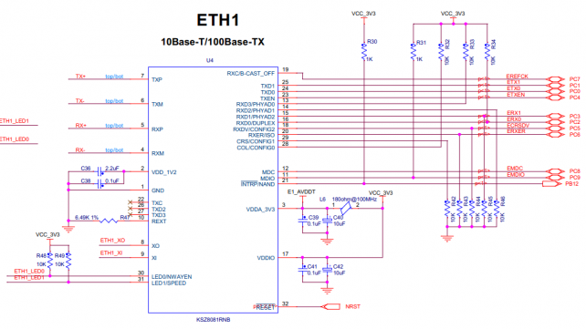
百兆以太网(Mbps ethernet)
接口丝印:J3。芯片丝印:U4。芯片型号:KSZ8081RNB。
silkscreen of interface:J3。silkscreen of chip:U4。chip model:KSZ8081RNB
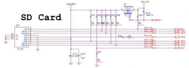
SD接口(SD port)
接口丝印:U23。
silkscreen of interface: U23
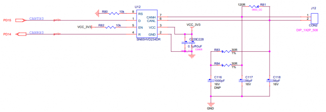
CAN0接口(CAN0 interface)
接口丝印:U12。
silkscreen of interface: U12
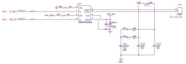
CAN1接口(CAN1 interface)
接口丝印:U13。
silkscreen of interface: U13
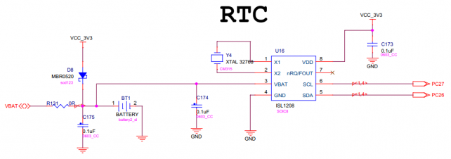
RTC
使用外部RTC。芯片丝印:U13。芯片型号:ISL1208
use external RTC。silkscreen of chip:U13。chip model:ISL1208
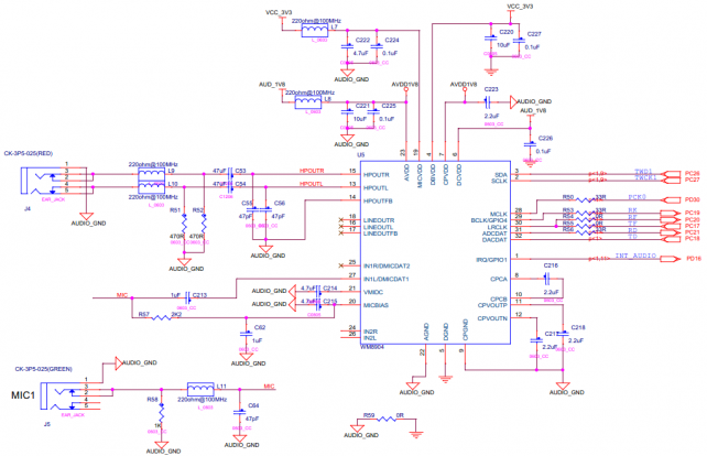
音频(WM8904)(audio(WM8904))
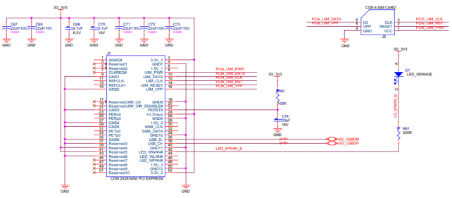
PCI-E
PCI-E接口丝印:J7。SIM卡接口丝印:J6
silkscreen of PCI-E: J7.silkscreen of SIM card:J6
GPS
芯片丝印:U22。模块型号:NEO-6M
silkscreen of chip: U22. module model:NEO-6M
