“MYZR-RK3288-MB314 硬件介绍”的版本间的差异
来自明远智睿的wiki
| 第1行: | 第1行: | ||
| − | |||
= '''接口概览(overview of interfaces)''' = | = '''接口概览(overview of interfaces)''' = | ||
---- | ---- | ||
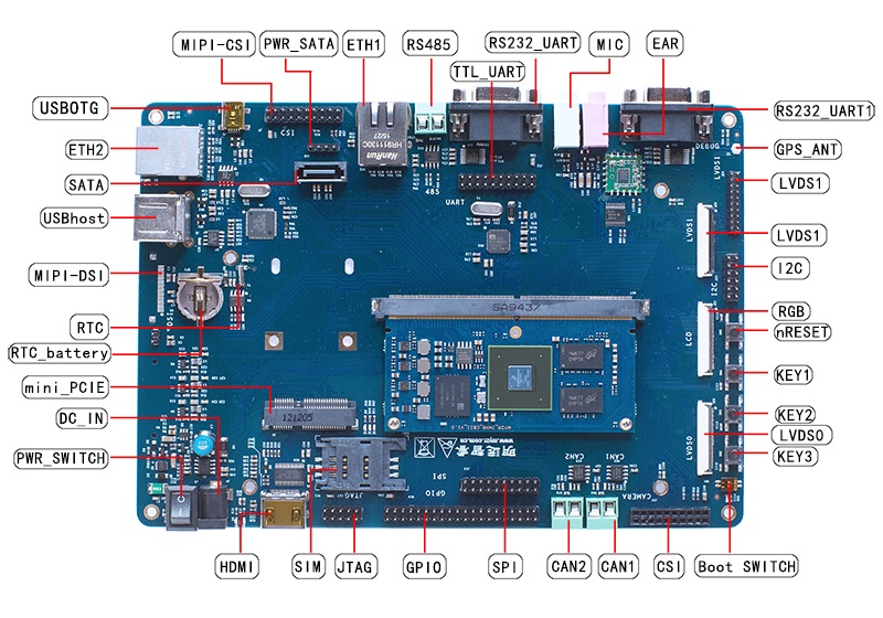
| − | == ''' | + | == '''正面图(MB314 + CB314)(front view(MB314+CB314)''' == |
| − | [[文件: | + | [[文件:MY-IMX6-MB314&CB314.jpg]] |
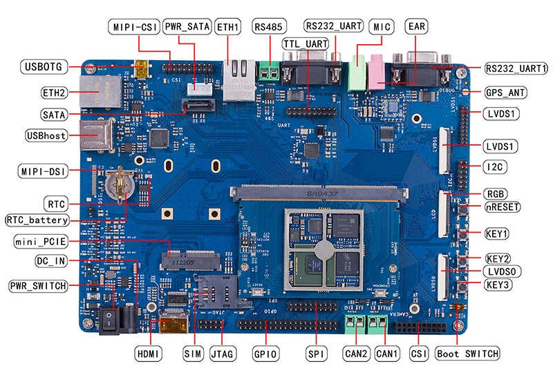
| − | == ''' | + | == '''正面图(MB314 + CB336)(front view(MB314+CB336)''' == |
| − | [[文件: | + | [[文件:MY-IMX6-MB314&CB336.jpg]] |
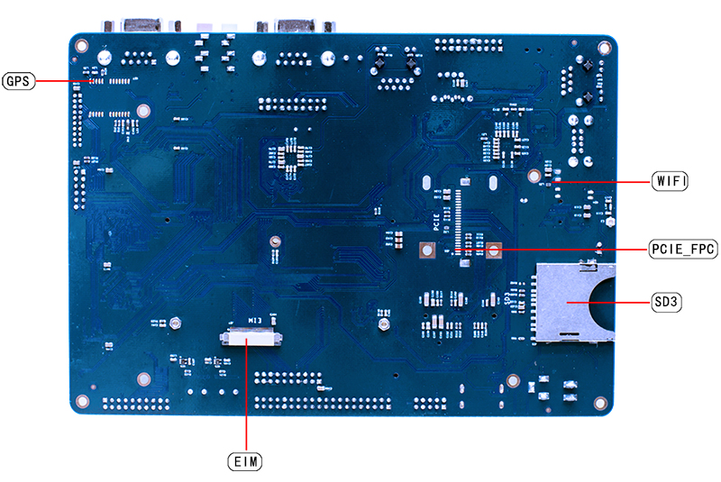
| − | == ''' | + | == '''背面图(MB314)(rear view(MB314))''' == |
| − | + | [[文件:MY-IMX6-MB314-Back.jpg]] | |
| − | |||
| − | |||
| − | |||
| − | |||
| − | |||
| − | |||
| − | |||
| − | |||
| − | |||
| − | |||
| − | |||
| − | |||
| − | |||
| − | |||
| − | |||
| − | |||
| − | |||
| − | |||
| − | |||
| − | |||
| − | |||
| − | |||
| − | |||
| − | |||
| − | |||
| − | |||
| − | |||
| − | |||
| − | |||
| − | |||
| − | |||
| − | |||
| − | |||
| − | |||
| − | |||
| − | |||
| − | |||
| − | |||
| − | |||
| − | |||
| − | |||
| − | |||
| − | |||
| − | |||
| − | |||
| − | |||
| − | |||
| − | |||
| − | |||
| − | |||
| − | |||
| − | |||
| − | |||
| − | |||
| − | |||
| − | |||
| − | |||
| − | |||
| − | |||
| − | |||
| − | |||
| − | |||
| − | |||
| − | |||
| − | |||
| − | |||
| − | |||
| − | |||
| − | |||
| − | |||
| − | |||
| − | |||
| − | |||
| − | |||
| − | |||
| − | |||
| − | |||
| − | |||
| − | |||
| − | |||
| − | |||
| − | |||
| − | |||
| − | |||
| − | |||
| − | |||
| − | |||
| − | |||
| − | |||
| − | |||
| − | |||
| − | |||
| − | |||
| − | |||
| − | |||
| − | |||
| − | |||
| − | |||
| − | |||
| − | |||
| − | |||
| − | |||
| − | |||
| − | |||
| − | |||
| − | |||
| − | |||
| − | |||
| − | |||
| − | |||
| − | |||
| − | |||
| − | |||
| − | |||
| − | |||
| − | |||
| − | |||
| − | |||
| − | |||
| − | |||
| − | |||
| − | |||
| − | |||
| − | |||
| − | |||
| − | |||
| − | |||
| − | |||
= '''接口功能(interface function)''' = | = '''接口功能(interface function)''' = | ||
---- | ---- | ||
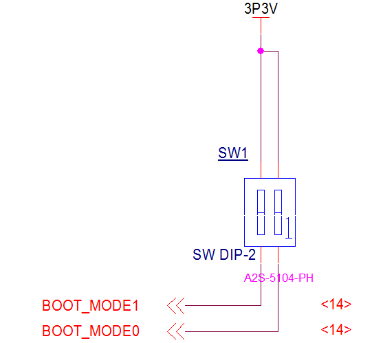
| − | == ''' | + | == '''两位拨码开关(2 bit dial switch) ''' == |
| + | 丝印(silk screen):SW1<br> | ||
| + | 引脚及信号定义如下:<br> | ||
| + | <span style="background:#CCCCCC">definition of pin & signal as below:</span><br> | ||
| + | [[文件:MY-IMX6-MB314-2.1.0.1.png|642px]]<br> | ||
{| class="wikitable" | {| class="wikitable" | ||
|- | |- | ||
| − | + | |模式控制 (mode control) | |
| − | + | |1位(1bit) | |
| − | + | |2位 (2bit) | |
|- | |- | ||
| − | | | + | |烧写模式 (burning mode) |
| − | | | + | |1 |
| − | | | + | |0 |
|- | |- | ||
| − | | | + | |启动模式 (booting mode) |
| − | | | + | |0 |
| − | | | + | |1 |
|} | |} | ||
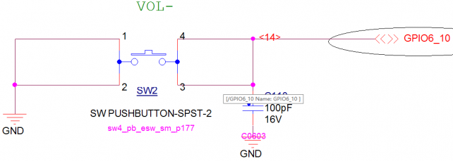
| + | == '''音量减(volume down)''' == | ||
| + | 丝印(silk screen):SW2<br> | ||
| + | 接口属性:音量控制(音量减)(interface property: volume control(volume down) <br> | ||
| + | 引脚及信号定义如下:<br> | ||
| + | <span style="background:#CCCCCC">definition of pin & signal as below:</span><br> | ||
| + | [[文件:MY-IMX6-MB314-2.2.0.1.png|642px]]<br> | ||
| + | == '''音量加(volume up)''' == | ||
| + | 丝印(silk screen):SW3<br> | ||
| + | 接口属性:音量控制(音量加)(interface property: volume control(volume up) <br> | ||
| + | 引脚及信号定义如下:<br> | ||
| + | <span style="background:#CCCCCC">definition of pin & signal as below:</span><br> | ||
| + | [[文件:MY-IMX6-MB314-2.3.0.1.png|642px]]<br> | ||
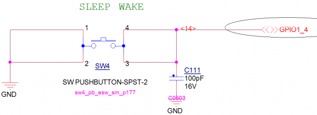
| + | == '''唤醒(wake up)''' == | ||
| + | 丝印(silk screen):SW4<br> | ||
| + | 接口属性:休眠唤醒(interface property:sleeping wake up) <br> | ||
| + | 引脚及信号定义如下:<br> | ||
| + | <span style="background:#CCCCCC">definition of pin & signal as below:</span><br> | ||
| + | [[文件:MY-IMX6-MB314-2.4.0.1.png|642px]]<br> | ||
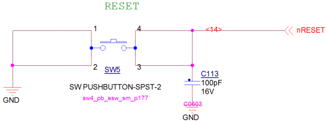
| + | == '''复位(reset)''' == | ||
| + | 丝印(silk screen):SW5<br> | ||
| + | 接口属性:系统复位(interface property: system reset)<br> | ||
引脚及信号定义如下:<br> | 引脚及信号定义如下:<br> | ||
<span style="background:#CCCCCC">definition of pin & signal as below:</span><br> | <span style="background:#CCCCCC">definition of pin & signal as below:</span><br> | ||
| − | [[文件: | + | [[文件:MY-IMX6-MB314-2.5.0.1.png|642px]]<br> |
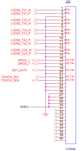
| − | + | == '''18/24bit LVDS0''' == | |
| + | 丝印(silk screen):J20<br> | ||
| + | LVDS0液晶是24bit模式,兼容18bit模式,通过此接口可连接明远智睿公司生产的不同尺寸规格的电阻LVDS液晶屏和电容LVDS液晶屏。LVDS0接口座采用了进口连接器,抛弃了国内便宜的抽屉式,采用的是对面按压式,保证安装更容易,性能,连接性更好。<br> | ||
| + | <span style="background:#CCCCCC">LVDS0 crystal liquid is 24bit mode,compatible to 18bit mode,through which LVDS resistance screen panel and LVDS capacitor screen panel in different sizes and specifications produced by MYZR can be connected, LVDS0 interface block is build with connector imported,abandon the cheap drawer type produced domestically,which is opposite press type to ensure easier installation, better performance and connectivity. <br> | ||
| + | |||
| + | 引脚及信号定义如下:<br> | ||
| + | <span style="background:#CCCCCC">definition of pin & signal as below:</span><br> | ||
| + | [[文件:MY-IMX6-MB314-2.6.0.1.png|642px]]<br> | ||
| + | |||
{| class="wikitable" | {| class="wikitable" | ||
|- | |- | ||
| − | + | |引脚 (pin) | |
| − | + | |信号 (signal) | |
| − | + | |描述 (description) | |
| − | + | |引脚 (pin) | |
| + | |信号 (signal) | ||
| + | |描述 (description) | ||
|- | |- | ||
| − | | | + | |J20-1 |
| − | | | + | |LVDS0_TX1_N |
| − | | | + | |rowspan=2|LVDS0差分数据1 (LVDS0 differential data 1) |
| − | | | + | |J20-21 |
| + | |TOUCH_SCL | ||
| + | |I2C时钟(I2C clock) | ||
|- | |- | ||
| − | | | + | |J20-2 |
| − | | | + | |LVDS0_TX1_P |
| − | | | + | |
| − | | | + | |J20-22 |
| + | |TOUCH_SDA | ||
| + | |I2C数据(I2C data) | ||
|- | |- | ||
| − | | | + | |J20-3 |
| − | | | + | |GND |
| − | | | + | |数字地 (digital ground) |
| − | | | + | |J20-23 |
| + | |rowspan=3|GND | ||
| + | |rowspan=3|数字地(digital ground) | ||
|- | |- | ||
| − | | | + | |J20-4 |
| − | | | + | |LVDS0_TX0_P |
| − | | | + | |rowspan=2|LVDS0差分数据0 (LVDS0 differential data 0 ) |
| − | + | |J20-24 | |
| + | |||
|- | |- | ||
| − | | | + | |J20-5 |
| − | | | + | |LVDS0_TX0_N |
| − | | | + | |
| − | + | |J20-25 | |
| + | |||
|- | |- | ||
| − | | | + | |J20-6 |
| − | | | + | |GND |
| − | | | + | |数字地 (digital ground) |
| − | | | + | |J20-26 |
| + | |rowspan=5|5VIN | ||
| + | |rowspan=5|5V输入(5V input) | ||
|- | |- | ||
| − | | | + | |J20-7 |
| − | | | + | |LVDS0_TX3_N |
| − | | | + | |rowspan=2|LVDS0差分数据3 (LVDS0 differential data 3 ) |
| − | + | |J20-27 | |
| + | |||
|- | |- | ||
| − | | | + | |J20-8 |
| − | | | + | |LVDS0_TX3_P |
| − | | | + | |
| − | + | |J20-28 | |
| − | |||
| + | |- | ||
| + | |J20-9 | ||
| + | |GND | ||
| + | |数字地 (digital ground) | ||
| + | |J20-29 | ||
| − | |||
| − | |||
| − | |||
| − | |||
| − | |||
| − | |||
| − | |||
| − | |||
|- | |- | ||
| − | + | |J20-10 | |
| − | + | |LVDS0_TX2_P | |
| − | + | |rowspan=2|LVDS0差分数据2 (LVDS0 differential data 2 ) | |
| − | + | |J20-30 | |
| + | |||
|- | |- | ||
| − | | | + | |J20-11 |
| − | | | + | |LVDS0_TX2_N |
| − | | | + | |
| − | |NC | + | |J20-31 |
| + | |rowspan=10|NC | ||
| + | |rowspan=10|悬空(dangling) | ||
|- | |- | ||
| − | | | + | |J20-12 |
| − | | | + | |GND |
| − | | | + | |数字地 (digital ground) |
| − | + | |J20-32 | |
| + | |||
|- | |- | ||
| − | | | + | |J20-13 |
| − | | | + | |LVDS0_CLK_N |
| − | | | + | |rowspan=2|LVDS0差分时钟 (LVDS0 differential clock) |
| − | + | |J20-33 | |
| + | |||
|- | |- | ||
| − | | | + | |J20-14 |
| − | | | + | |LVDS0_CLK_P |
| − | | | + | |
| − | + | |J20-34 | |
| + | |||
|- | |- | ||
| − | | | + | |J20-15 |
| − | | | + | |GND |
| − | | | + | |数字地 (digital ground) |
| − | + | |J20-35 | |
| + | |||
|- | |- | ||
| − | | | + | |J20-16 |
| − | | | + | |SD1_DAT1/TOUCH_nEINT1 |
| − | | | + | |rowspan=2|GPIO控制 (GPIO control) |
| − | + | |J20-36 | |
| + | |||
|- | |- | ||
| − | | | + | |J20-17 |
| − | | | + | |NANDF_CS3 |
| − | | | + | |
| − | + | |J20-37 | |
| + | |||
|- | |- | ||
| − | | | + | |J20-18 |
| − | | | + | |GND |
| − | | | + | |数字地 (digital ground) |
| − | + | |J20-38 | |
| + | |||
|- | |- | ||
| − | | | + | |J20-19 |
| − | | | + | |DISP0_CONTRAST |
| − | | | + | |LVDS0背光调节 (LVDS0 backlight adjustment) |
| − | + | |J20-39 | |
| + | |||
|- | |- | ||
| − | | | + | |J20-20 |
| − | |GND | + | |GND |
| − | | | + | |数字地 (digital ground) |
| − | | | + | |J20-40 |
| + | |||
|} | |} | ||
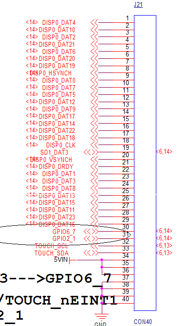
| + | == '''18/24bit RGB''' == | ||
| + | 丝印(silk screen):J21<br> | ||
| + | RGB液晶是24bit模式,兼容18bit/16bit模式,通过此接口可连接明远智睿公司生产的不同尺寸规格的电阻RGB液晶屏和电容RGB液晶屏。RGB液晶接口座采用了进口连接器,抛弃了国内便宜的抽屉式,采用的是对面按压式,保证安装更容易,性能,连接性更好。<br> | ||
| + | <span style="background:#CCCCCC">RGB crystal liquid is 24bit mode,compatible to 18bit/16bit mode,through which RGB resistance screen panel and RGB capacitor screen panel in different sizes and specifications produced by MYZR can be connected,RGB interface block is build with connector imported,abandon the cheap drawer type produced domestically,which is opposite press type to ensure easier installation,better performance and connectivity. <br> | ||
| − | + | 引脚及信号定义如下:<br> | |
| − | + | <span style="background:#CCCCCC">definition of pin & signal as below:</span><br> | |
| − | + | [[文件:MY-IMX6-MB314-2.7.0.1.png|642px]]<br> | |
| − | |||
| − | |||
| − | <span style="background:#CCCCCC">definition of pin & | ||
| − | [[文件: | ||
{| class="wikitable" | {| class="wikitable" | ||
|- | |- | ||
| − | + | |引脚 (pin) | |
| − | + | |信号 (signal) | |
| − | + | |描述 (description) | |
| − | + | |引脚 (pin) | |
| + | |信号 (signal) | ||
| + | |描述 (description) | ||
|- | |- | ||
| − | | | + | |J21-1 |
| − | | | + | |DISP0_DAT4 |
| − | | | + | |LCD数据4 (LCD data 4) |
| − | | | + | |J21-21 |
| + | |DISP0_DRDY | ||
| + | |LCD_DataEn | ||
|- | |- | ||
| − | | | + | |J21-2 |
| − | | | + | |DISP0_DAT10 |
| − | | | + | |LCD数据10 (LCD data 10) |
| − | | | + | |J21-22 |
| + | |DISP0_DAT1 | ||
| + | |LCD数据1 (LCD data 1) | ||
|- | |- | ||
| − | | | + | |J21-3 |
| − | | | + | |DISP0_DAT2 |
| − | | | + | |LCD数据2 (LCD data 2) |
| − | | | + | |J21-23 |
| + | |DISP0_DAT3 | ||
| + | |LCD数据3 (LCD data 3) | ||
|- | |- | ||
| − | | | + | |J21-4 |
| − | | | + | |DISP0_DAT21 |
| − | | | + | |LCD数据21 (LCD data 21) |
| − | | | + | |J21-24 |
| + | |DISP0_DAT8 | ||
| + | |LCD数据8 (LCD data 8) | ||
|- | |- | ||
| − | | | + | |J21-5 |
| − | | | + | |DISP0_DAT6 |
| − | | | + | |LCD数据6 (LCD data 6) |
| − | | | + | |J21-25 |
| + | |DISP0_DAT13 | ||
| + | |LCD数据13 (LCD data 13) | ||
|- | |- | ||
| − | | | + | |J21-6 |
| − | | | + | |DISP0_DAT20 |
| − | | | + | |LCD数据20 (LCD data 20) |
| − | | | + | |J21-26 |
| + | |DISP0_DAT15 | ||
| + | |LCD数据15 (LCD data 15) | ||
|- | |- | ||
| − | | | + | |J21-7 |
| − | | | + | |DISP0_DAT19 |
| − | | | + | |LCD数据19 (LCD data 19) |
| − | | | + | |J21-27 |
| − | | | + | |DISP0_DAT11 |
| − | + | |LCD数据11 (LCD data 11) | |
| − | + | |- | |
| − | + | |J21-8 | |
| − | + | |DISP0_HSYNCH | |
| − | + | |LCD行时钟 (LCD row clock) | |
| − | + | |J21-28 | |
| − | + | |DISP0_DAT23 | |
| − | + | |LCD数据23 (LCD data 23) | |
| − | + | |- | |
| − | + | |J21-9 | |
| + | |DISP0_DAT0 | ||
| + | |LCD数据0 (LCD data 0) | ||
| + | |J21-29 | ||
| + | |DISP0_DAT16 | ||
| + | |LCD数据16 (LCD data 16) | ||
|- | |- | ||
| − | + | |J21-10 | |
| − | + | |DISP0_DAT7 | |
| − | + | |LCD数据7 (LCD data 7) | |
| − | + | |J21-30 | |
| + | |NANDF_CS3 | ||
| + | |rowspan=2|GPIO控制(GPIO control) | ||
|- | |- | ||
| − | | | + | |J21-11 |
| − | | | + | |DISP0_DAT5 |
| − | | | + | |LCD数据5 (LCD data 5) |
| − | | | + | |J21-31 |
| + | |SD1_DAT1/TOUCH_nEINT1 | ||
| + | |||
|- | |- | ||
| − | | | + | |J21-12 |
| − | | | + | |DISP0_DAT12 |
| − | | | + | |LCD数据12 (LCD data 12) |
| − | | | + | |J21-32 |
| + | |TOUCH_SCL | ||
| + | |I2C时钟 (I2C clock) | ||
|- | |- | ||
| − | | | + | |J21-13 |
| − | | | + | |DISP0_DAT9 |
| − | | | + | |LCD数据9 (LCD data 9) |
| − | | | + | |J21-33 |
| + | |TOUCH_SDA | ||
| + | |I2C数据 (I2C data) | ||
|- | |- | ||
| − | | | + | |J21-14 |
| − | | | + | |DISP0_DAT17 |
| − | | | + | |LCD数据17 (LCD data 17) |
| − | | | + | |J21-34 |
| + | |rowspan=3|5VIN | ||
| + | |rowspan=3|5V输入 (5V input) | ||
|- | |- | ||
| − | | | + | |J21-15 |
| − | | | + | |DISP0_DAT14 |
| − | | | + | |LCD数据14 (LCD data 14) |
| − | + | |J21-35 | |
| + | |||
|- | |- | ||
| − | | | + | |J21-16 |
| − | | | + | |DISP0_DAT22 |
| − | | | + | |LCD数据22 (LCD data 22) |
| − | + | |J21-36 | |
| + | |||
|- | |- | ||
| − | | | + | |J21-17 |
| − | | | + | |DISP0_DAT18 |
| − | | | + | |LCD数据18 (LCD data 18) |
| − | |GND | + | |J21-37 |
| + | |rowspan=4|GND | ||
| + | |rowspan=4|数字地 (digital ground) | ||
|- | |- | ||
| − | | | + | |J21-18 |
| − | | | + | |DISP0_CLK |
| − | | | + | |LCD点时钟 (LCD dot clock) |
| − | + | |J21-38 | |
| + | |||
|- | |- | ||
| − | | | + | |J21-19 |
| − | | | + | |DISP0_CONTRAST |
| − | | | + | |LCD背光调节(LCD backlight adjustment) |
| − | + | |J21-39 | |
| + | |||
|- | |- | ||
| − | | | + | |J21-20 |
| − | | | + | |DISP0_VSYNCH |
| − | | | + | |LCD帧时钟 (LCD frame clock) |
| − | + | |J21-40 | |
| + | |||
|} | |} | ||
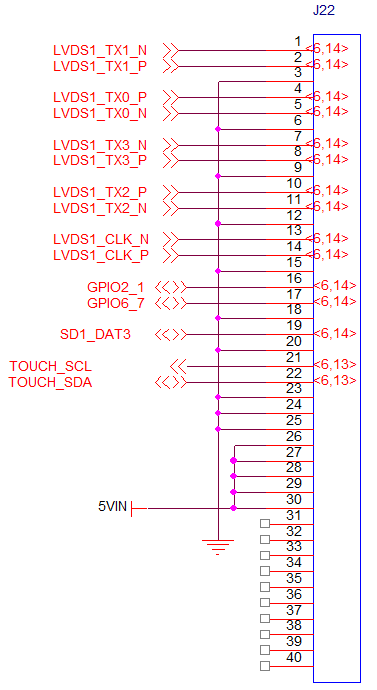
| + | == '''18/24bit LVDS1''' == | ||
| + | 丝印(silk screen):J22<br> | ||
| + | LVDS1液晶接口跟LVDS0液晶接口定义,接插件型号完全一样,用户可以直接把LVDS0处的液晶直接接到LVDS1处。<br> | ||
| + | <span style="background:#CCCCCC">LVDS1 crystal liquid interface is the same as LVDS0 in terms of definition and connector model,users can connect crytal liquid in LVDS0 directly to LVDS1. <br> | ||
| − | + | 引脚及信号定义如下:<br> | |
| − | + | <span style="background:#CCCCCC">definition of pin & signal as below:</span><br> | |
| − | + | [[文件:MY-IMX6-MB314-2.8.0.1.png|642px]]<br> | |
| − | |||
| − | |||
| − | <span style="background:#CCCCCC">definition of pin & | ||
| − | [[文件: | ||
{| class="wikitable" | {| class="wikitable" | ||
|- | |- | ||
| − | + | |引脚 (pin) | |
| − | + | |信号 (signal) | |
| − | + | |描述 (description) | |
| − | + | |引脚 (pin) | |
| + | |信号 (signal) | ||
| + | |描述 (description) | ||
| + | |- | ||
| + | |J22-1 | ||
| + | |LVDS1_TX1_N | ||
| + | |rowspan=2|LVDS1差分数据1 (LVDS1 differential data 1) | ||
| + | |J22-21 | ||
| + | |TOUCH_SCL | ||
| + | |I2C时钟 (I2C clock) | ||
|- | |- | ||
| − | | | + | |J22-2 |
| − | | | + | |LVDS1_TX1_P |
| − | | | + | |
| − | | | + | |J22-22 |
| + | |TOUCH_SDA | ||
| + | |I2C数据(I2C clock) | ||
|- | |- | ||
| − | | | + | |J22-3 |
|GND | |GND | ||
| − | | | + | |数字地 (digital ground) |
| − | | | + | |J22-23 |
| + | |rowspan=3|GND | ||
| + | |rowspan=3|数字地 (digital ground) | ||
|- | |- | ||
| − | | | + | |J22-4 |
| − | | | + | |LVDS1_TX1_P |
| − | | | + | |rowspan=2|LVDS1差分数据1 (LVDS1 differential data 1) |
| − | + | |J22-24 | |
| + | |||
|- | |- | ||
| − | | | + | |J22-5 |
| − | | | + | |LVDS1_TX1_N |
| − | | | + | |
| − | + | |J22-25 | |
| + | |||
|- | |- | ||
| − | | | + | |J22-6 |
| − | | | + | |GND |
| − | | | + | |数字地(digital ground) |
| − | | | + | |J22-26 |
| + | |rowspan=5|5VIN | ||
| + | |rowspan=5|5V输入(5V input) | ||
|- | |- | ||
| − | | | + | |J22-7 |
| − | | | + | |LVDS1_TX3_N |
| − | | | + | |rowspan=2|LVDS1差分数据3 (LVDS1 differential data 3) |
| − | + | |J22-27 | |
| + | |||
|- | |- | ||
| − | | | + | |J22-8 |
| − | | | + | |LVDS1_TX3_P |
| − | | | + | |
| − | + | |J22-28 | |
| + | |||
|- | |- | ||
| − | | | + | |J22-9 |
| − | | | + | |GND |
| − | | | + | |数字地 (digital ground) |
| − | + | |J22-29 | |
| + | |||
|- | |- | ||
| − | | | + | |J22-10 |
| − | | | + | |LVDS1_TX2_P |
| − | | | + | |rowspan=2|LVDS1差分数据2 (LVDS1 differential data 2) |
| − | + | |J22-30 | |
| + | |||
|- | |- | ||
| − | | | + | |J22-11 |
| − | | | + | |LVDS1_TX2_N |
| − | | | + | |
| − | | | + | |J22-31 |
| + | |rowspan=10|NC | ||
| + | |rowspan=10|悬空(dangling) | ||
|- | |- | ||
| − | | | + | |J22-12 |
| − | | | + | |GND |
| − | | | + | |数字地 (digital ground) |
| − | | | + | |J22-32 |
|- | |- | ||
| − | | | + | |J22-13 |
| − | | | + | |LVDS1_CLK_N |
| − | | | + | |rowspan=2|LVDS1差分时钟 (LVDS1 difference clock) |
| − | | | + | |J22-33 |
| − | | | ||
| + | |- | ||
| + | |J22-14 | ||
| + | |LVDS1_CLK_P | ||
| + | |||
| + | |J22-34 | ||
| − | |||
| − | |||
| − | |||
| − | |||
| − | |||
| − | |||
| − | |||
| − | |||
|- | |- | ||
| − | + | |J22-15 | |
| − | + | |GND | |
| − | + | |数字地 (digital ground) | |
| − | + | |J22-35 | |
| + | |||
|- | |- | ||
| − | | | + | |J22-16 |
| − | | | + | |SD1_DAT1/TOUCH_nEINT1 |
| − | | | + | |rowspan=2|GPIO控制 (GPIO control) |
| − | + | |J22-36 | |
| + | |||
|- | |- | ||
| − | | | + | |J22-17 |
| − | | | + | |NANDF_CS3 |
| − | | | + | |
| − | + | |J22-37 | |
| + | |||
|- | |- | ||
| − | | | + | |J22-18 |
| − | | | + | |GND |
| − | | | + | |数字地 (digital ground) |
| − | + | |J22-38 | |
| + | |||
|- | |- | ||
| − | | | + | |J22-19 |
| − | | | + | |DISP1_CONTRAST |
| − | | | + | |LVDS1背光调节 (LVDS1 backlight adjustment) |
| − | + | |J22-39 | |
| + | |||
|- | |- | ||
| − | | | + | |J22-20 |
| − | |GND | + | |GND |
| − | | | + | |数字地 (digital ground) |
| − | | | + | |J22-40 |
| + | |||
| + | |} | ||
| + | |||
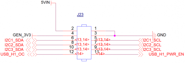
| + | == '''I2C扩展(I2C expansion)''' == | ||
| + | 丝印(silk screen):J23<br> | ||
| + | 引脚及信号定义如下:<br> | ||
| + | <span style="background:#CCCCCC">definition of pin & signal as below:</span><br> | ||
| + | [[文件:MY-IMX6-MB314-2.9.0.1.png|642px]]<br> | ||
| + | {| class="wikitable" | ||
|- | |- | ||
| − | | | + | |引脚 (pin) |
| − | | | + | |信号 (signal) |
| − | | | + | |描述 (description) |
| − | | | + | |引脚 (pin) |
| + | |信号 (signal) | ||
| + | |描述 (description) | ||
|- | |- | ||
| − | | | + | |J23-1 |
| − | |GND | + | |GND |
| − | | | + | |数字地 (digital ground) |
| − | | | + | |J23-2 |
| + | |5VIN | ||
| + | |5V输入 (5V input) | ||
|- | |- | ||
| − | | | + | |J23-3 |
| − | | | + | |GND |
| − | | | + | |数字地 (digital ground) |
| − | | | + | |J23-4 |
| + | |GEN_3V3 | ||
| + | |3.3V输入(3.3V input) | ||
|- | |- | ||
| − | | | + | |J23-5 |
| − | | | + | |I2C1_SCL |
| − | | | + | |I2C1时钟 (I2C1 clock) |
| − | | | + | |J23-6 |
| + | |I2C1_SDA | ||
| + | |I2C1数据 (I2C1 data) | ||
|- | |- | ||
| − | | | + | |J23-7 |
| − | | | + | |I2C2_SCL |
| − | | | + | |I2C2时钟 (I2C2 clock) |
| − | | | + | |J23-8 |
| + | |I2C2_SDA | ||
| + | |I2C2数据 (I2C2 data) | ||
|- | |- | ||
| − | | | + | |J23-9 |
| − | | | + | |I2C3_SCL |
| − | | | + | |I2C3时钟 (I2C3 clock) |
| − | | | + | |J23-10 |
| + | |I2C3_SDA | ||
| + | |I2C3数据 (I2C3 data) | ||
|- | |- | ||
| − | | | + | |J23-11 |
| − | | | + | |USB_H1_PWR_EN |
| − | | | + | |GPIO |
| − | + | |J23-12 | |
| − | + | |USB_H1_OC | |
| − | + | |GPIO | |
| − | |||
| − | |||
| − | |||
| − | |- | ||
| − | | | ||
| − | |||
| − | |||
| − | | | ||
|} | |} | ||
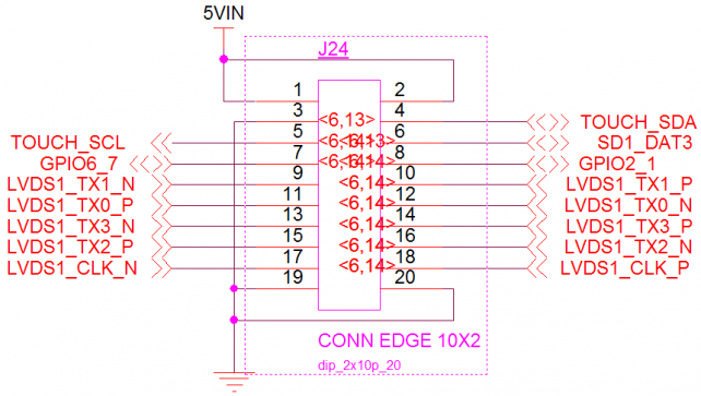
| − | + | == '''18/24bit LVDS1扩展(18/24bit LVDS1 expansion)''' == | |
| − | == ''' | + | 丝印(slik screen) :J24 <br> |
| − | 丝印( | + | 引脚及信号定义如下:<br> |
| − | + | <span style="background:#CCCCCC">definition of pin & signal as below:</span><br> | |
| − | + | [[文件:MY-IMX6-MB314-2.10.0.1.png|642px]]<br> | |
| − | |||
| − | <span style="background:#CCCCCC">definition of pin & | ||
| − | [[文件: | ||
{| class="wikitable" | {| class="wikitable" | ||
|- | |- | ||
| − | + | |引脚 (pin) | |
| − | + | |信号 (signal) | |
| − | + | |描述 (description) | |
| − | + | |引脚 (pin) | |
| + | |信号 (signal) | ||
| + | |描述 (description) | ||
|- | |- | ||
| − | | | + | |J24-1 |
| − | | | + | |5VIN |
| − | | | + | |5V输入 (5V input) |
| − | | | + | |J24-2 |
| + | |5VIN | ||
| + | |5V输入 (5V input) | ||
|- | |- | ||
| − | | | + | |J24-3 |
| − | | | + | |GND |
| − | | | + | |数字地 (digital ground) |
| − | | | + | |J24-4 |
| + | |TOUCH_SDA | ||
| + | |I2C3数据 (I2C3 data) | ||
|- | |- | ||
| − | | | + | |J24-5 |
| − | | | + | |TOUCH_SCL |
| − | | | + | |I2C3时钟 (I2C3 clock) |
| − | | | + | |J24-6 |
| + | |DISP0_CNTRST | ||
| + | |背光使能 (backlight enabling) | ||
|- | |- | ||
| − | | | + | |J24-7 |
| − | | | + | |GPIO6_7 |
| − | | | + | |GPIO |
| − | | | + | |J24-8 |
| + | |GPIO2_1 | ||
| + | |GPIO | ||
|- | |- | ||
| − | | | + | |J24-9 |
| − | | | + | |LVDS1_TX1_N |
| − | | | + | |LVDS1差分数据1 (LVDS1 differential data1) |
| − | | | + | |J24-10 |
| + | |LVDS1_TX1_P | ||
| + | |LVDS1差分数据1 (LVDS1 differential data1) | ||
|- | |- | ||
| − | | | + | |J24-11 |
| − | | | + | |LVDS1_TX0_P |
| − | | | + | |LVDS1差分数据0 (LVDS1 differential data 0) |
| − | | | + | |J24-12 |
| + | |LVDS1_TX0_N | ||
| + | |LVDS1差分数据0 (LVDS1 differential data 0) | ||
|- | |- | ||
| − | | | + | |J24-13 |
| − | | | + | |LVDS1_TX3_N |
| − | | | + | |LVDS1差分数据3 (LVDS1 differential data 3) |
| − | | | + | |J24-14 |
| + | |LVDS1_TX3_P | ||
| + | |LVDS1差分数据3 (LVDS1 differential data 3) | ||
|- | |- | ||
| − | | | + | |J24-15 |
| − | | | + | |LVDS1_TX2_P |
| − | | | + | |LVDS1差分数据2 (LVDS1 differential data 2) |
| − | | | + | |J24-16 |
| + | |LVDS1_TX2_N | ||
| + | |LVDS1差分数据2 (LVDS1 differential data 2) | ||
|- | |- | ||
| − | | | + | |J24-17 |
| − | | | + | |LVDS1_CLK_N |
| − | | | + | |LVDS1差分时钟 (LVDS1 differential clock) |
| − | | | + | |J24-18 |
| + | |LVDS1_CLK_P | ||
| + | |LVDS1差分时钟 (LVDS1 differential clock) | ||
|- | |- | ||
| − | | | + | |J24-19 |
| − | + | |GND | |
| − | + | |数字地 (digital ground) | |
| − | |GND | + | |J24-20 |
| − | | | + | |GND |
| − | + | |数字地 (digital ground) | |
| − | |||
| − | |||
| − | |||
| − | |||
| − | | | ||
| − | |GND | ||
| − | | | ||
| − | |||
| − | |||
| − | |||
| − | |||
| − | |||
| − | |||
|} | |} | ||
| − | + | == '''GPS天线座(GPS antenna pedestal)''' == | |
| − | == ''' | + | 丝印(silk screen):E2<br> |
| − | 丝印( | + | 接口属性(interface property):天线座 (antenna pedestal)<br> |
| − | + | 引脚及信号定义如下:<br> | |
| − | <span style="background:#CCCCCC"> | + | <span style="background:#CCCCCC">definition of pin & signal as below:</span><br> |
| − | + | [[文件:MY-IMX6-MB314-2.11.0.1.png|642px]]<br> | |
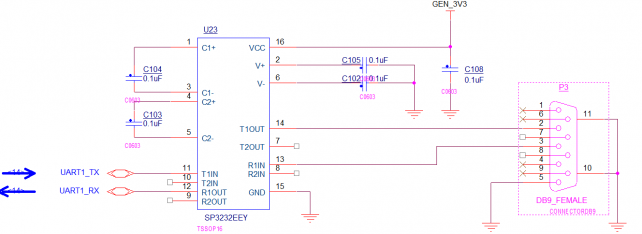
| − | <span style="background:#CCCCCC">definition of pin & | + | == '''调试串口(debug serial port) ''' == |
| − | [[文件: | + | 丝印(silk screen):P3<br> |
| + | 接口属性(interface property):UART0,232电平,调试串口(UART0,232 electrical Level, debug serial port)<br> | ||
| + | 引脚及信号定义如下:<br> | ||
| + | <span style="background:#CCCCCC">definition of pin & signal as below:</span><br> | ||
| + | [[文件:MY-IMX6-MB314-2.12.0.1.png|642px]]<br> | ||
| + | == '''耳机输出(headphone output)''' == | ||
| + | 丝印(silk screen):J16<br> | ||
| + | 接口属性(interface property):音频信号输出,3.5mm接口(audio signal output, 3.5mm interface)<br> | ||
| + | 引脚及信号定义如下:<br> | ||
| + | <span style="background:#CCCCCC">definition of pin & signal as below:</span><br> | ||
| + | [[文件:MY-IMX6-MB314-2.13.0.1.png|642px]]<br> | ||
| + | == '''麦克风输入(MIC)''' == | ||
| + | 丝印(silk screen):J14<br> | ||
| + | 接口属性(interface property):音频信号输入,3.5mm接口(audio signal input, 3.5mm interface)<br> | ||
| + | 引脚及信号定义如下:<br> | ||
| + | <span style="background:#CCCCCC">definition of pin & signal as below:</span><br> | ||
| + | [[文件:MY-IMX6-MB314-2.14.0.1.png|642px]]<br> | ||
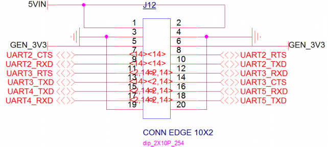
| + | == '''串口扩展/TTL电平(serial port extension/TTL electrical level)''' == | ||
| + | 丝印(silk screen):J12<br> | ||
| + | 引脚及信号定义如下:<br> | ||
| + | <span style="background:#CCCCCC">definition of pin & signal as below:</span><br> | ||
| + | [[文件:MY-IMX6-MB314-2.15.0.1.png|642px]]<br> | ||
{| class="wikitable" | {| class="wikitable" | ||
|- | |- | ||
| − | + | |引脚 (pin) | |
| − | + | |信号 (signal) | |
| − | + | |描述 (description) | |
| − | + | |引脚 (pin) | |
| + | |信号 (pin) | ||
| + | |描述 (description) | ||
|- | |- | ||
| − | | | + | |J12-1 |
| − | | | + | |5VIN |
| − | | | + | |5V输入 (5V input) |
| − | | | + | |J12-2 |
| + | |5VIN | ||
| + | |5V输入(5V input) | ||
|- | |- | ||
| − | | | + | |J12-3 |
| + | |GND | ||
| + | |数字地 (digital ground) | ||
| + | |J12-4 | ||
|GND | |GND | ||
| − | | | + | |数字地 (digital ground) |
| − | |||
|- | |- | ||
| − | | | + | |J12-5 |
| − | | | + | |GEN_3V3 |
| − | | | + | |3.3V输入 (3.3v input) |
| − | | | + | |J12-6 |
| + | |GEN_3V3 | ||
| + | |3.3V输入 (3.3v input) | ||
|- | |- | ||
| − | | | + | |J12-7 |
| − | | | + | |UART2_CTS |
| − | | | + | |串口2清除发送 (serial port 2 CTS) |
| − | | | + | |J12-8 |
| + | |UART2_RTS | ||
| + | |串口2请求发送 (serial port 2 RTS) | ||
|- | |- | ||
| − | | | + | |J12-9 |
| − | | | + | |UART2_RXD |
| − | | | + | |串口2接收 (serial port 2 receiving) |
| − | | | + | |J12-10 |
| + | |UART2_TXD | ||
| + | |串口2发送 (serial port 2 sending) | ||
|- | |- | ||
| − | | | + | |J12-11 |
| − | | | + | |UART3_RTS |
| − | | | + | |串口3请求发送 (serial port 3 RTS) |
| − | | | + | |J12-12 |
| + | |UART3_RXD | ||
| + | |串口3接收 (serial port 3 receiving) | ||
|- | |- | ||
| − | | | + | |J12-13 |
| − | | | + | |UART3_TXD |
| − | | | + | |串口3发送 (serial port 3 sending) |
| − | | | + | |J12-14 |
| + | |UART3_CTS | ||
| + | |串口3清除发送 (serial port 3 sending) | ||
|- | |- | ||
| − | | | + | |J12-15 |
| − | | | + | |UART4_TXD |
| − | | | + | |串口4发送 (serial port 4 sending) |
| − | | | + | |J12-16 |
| + | |UART5_RXD | ||
| + | |串口5接收 (serial port 5 receiving) | ||
|- | |- | ||
| − | | | + | |J12-17 |
| − | | | + | |UART4_RXD |
| − | | | + | |串口4接收 (serial port 4 receiving) |
| − | | | + | |J12-18 |
| + | |UART5_TXD | ||
| + | |串口5发送 (serial port 5 sending) | ||
|- | |- | ||
| − | | | + | |J12-19 |
| − | + | |GND | |
| − | + | |数字地 (digital ground) | |
| − | + | |J12-20 | |
| − | + | |GND | |
| − | + | |数字地 (digital ground) | |
| − | |GND | ||
| − | | | ||
| − | |||
| − | |||
| − | |||
| − | |||
| − | |||
| − | |||
| − | |||
| − | |||
| − | |||
| − | |||
| − | |||
| − | |||
| − | | | ||
| − | |||
| − | |||
| − | |||
| − | |||
| − | |||
| − | |GND | ||
| − | | | ||
| − | |||
|} | |} | ||
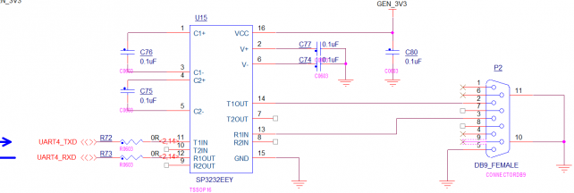
| − | + | == '''232串口(232 serial port)''' == | |
| − | == ''' | + | 丝印(silk screen):P2<br> |
| − | 丝印( | + | 接口属性(interface property):UART4,RS-232,应用串口(UART4, RS-232, application serial port)<br> |
| − | + | 引脚及信号定义如下:<br> | |
| − | <span style="background:#CCCCCC">interface | + | <span style="background:#CCCCCC">definition of pin & signal as below:</span><br> |
| − | + | [[文件:MY-IMX6-MB314-2.16.0.1.png|642px]]<br> | |
| − | <span style="background:#CCCCCC">definition of pin & | + | == '''485串口(485 serial port)''' == |
| − | [[文件: | + | 丝印(silk screen):J11<br> |
| + | 接口属性(interface property):UART3,RS-485,应用串口(UART3, RS-485, application serial port)<br> | ||
| + | 引脚及信号定义如下:<br> | ||
| + | <span style="background:#CCCCCC">definition of pin & signal as below:</span><br> | ||
| + | [[文件:MY-IMX6-MB314-2.17.0.1.png|642px]]<br> | ||
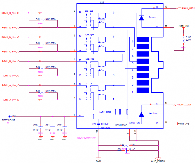
| + | == '''RGMII''' == | ||
| + | 丝印(silk screen):U12<br> | ||
| + | 接口属性:千兆网接口(interface property: GigE Vision)<br> | ||
| + | 引脚及信号定义如下:<br> | ||
| + | <span style="background:#CCCCCC">definition of pin & signal as below:</span><br> | ||
| + | [[文件:MY-IMX6-MB314-2.18.0.1.png|642px]]<br> | ||
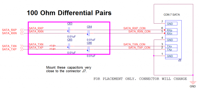
| + | == '''SATA II''' == | ||
| + | 丝印(silk screen):J9<br> | ||
| + | 接口属性:3Gbps SATA II接口(interface property:3Gbps SATA I interface)<br> | ||
| + | 引脚及信号定义如下:<br> | ||
| + | <span style="background:#CCCCCC">definition of pin & signal as below:</span><br> | ||
| + | [[文件:MY-IMX6-MB314-2.19.0.1.png|642px]]<br> | ||
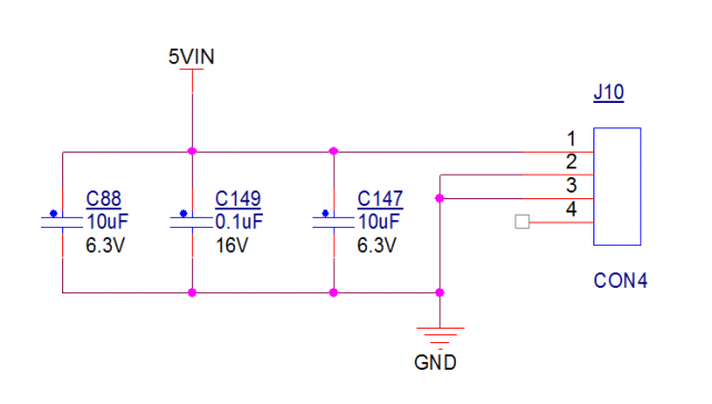
| + | == '''SATA电源(SATA power supply)''' == | ||
| + | 丝印(silk screen):J10<br> | ||
| + | 引脚及信号定义如下:<br> | ||
| + | <span style="background:#CCCCCC">definition of pin & signal as below:</span><br> | ||
| + | [[文件:MY-IMX6-MB314-2.20.0.1.png|642px]]<br> | ||
{| class="wikitable" | {| class="wikitable" | ||
|- | |- | ||
| − | + | |引脚 (pin) | |
| − | + | |信号 (signal) | |
| − | + | |描述 (description) | |
| − | |||
|- | |- | ||
| − | | | + | |J10-1 |
| − | | | + | |5VIN |
| − | | | + | |5V电源输入 (5V power input) |
| − | |||
|- | |- | ||
| − | | | + | |J10-2 |
|GND | |GND | ||
| − | | | + | |数字地 (digital ground) |
| − | |||
|- | |- | ||
| − | | | + | |J10-3 |
| − | | | + | |GND |
| − | | | + | |数字地 (digital ground) |
| − | | | + | |- |
| + | |J10-4 | ||
| + | |NC | ||
| + | |未连接(unconnected) | ||
|} | |} | ||
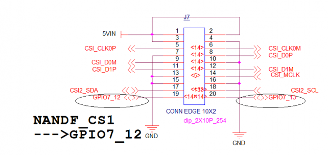
| − | + | == '''MIPI-CSI''' == | |
| − | == ''' | + | 丝印(silk screen):J7<br> |
| − | 丝印( | + | 引脚及信号定义如下:<br> |
| − | + | <span style="background:#CCCCCC">definition of pin & signal as below:</span><br> | |
| − | + | [[文件:MY-IMX6-MB314-2.21.0.1.png|642px]]<br> | |
| − | |||
| − | <span style="background:#CCCCCC">definition of pin & | ||
| − | [[文件: | ||
{| class="wikitable" | {| class="wikitable" | ||
|- | |- | ||
| − | + | |引脚(pin) | |
| − | + | |信号 (signal) | |
| − | + | |描述 (description) | |
| − | + | |引脚 (pin) | |
| + | |信号 (signal) | ||
| + | |描述 (description) | ||
|- | |- | ||
| − | | | + | |J7-1 |
| − | |5V | + | |5VIN |
| − | | | + | |5V输入 (5V input) |
| − | |5V | + | |J7-2 |
| + | |5VIN | ||
| + | |5V输入(5V input) | ||
|- | |- | ||
| − | | | + | |J7-3 |
| − | |5V | + | |5VIN |
| − | | | + | |5V输入 (5V input) |
| − | |GND | + | |J7-4 |
| + | |GND | ||
| + | |数字地 (digital ground) | ||
|- | |- | ||
| − | | | + | |J7-5 |
| − | | | + | |CSI_CLK0P |
| − | | | + | |CSI差分时钟 (CSI differential clock) |
| − | | | + | |
| + | |J7-6 | ||
| + | |CSI_CLK0M | ||
| + | |CSI差分时钟 (CSI differential clock) | ||
|- | |- | ||
| − | | | + | |J7-7 |
| − | | | + | |GND |
| − | | | + | |数字地 (digital ground) |
| − | | | + | |J7-8 |
| + | |CSI_D0P | ||
| + | |CSI差分数据0 (CSI differential data 0) | ||
|- | |- | ||
| − | | | + | |J7-9 |
| − | | | + | |CSI_D0M |
| − | | | + | |CSI差分数据0 (CSI differential data 0) |
| − | | | + | |J7-10 |
| + | |GND | ||
| + | |数字地 (digital ground) | ||
|- | |- | ||
| − | | | + | |J7-11 |
| − | | | + | |CSI_D1P |
| − | | | + | |CSI差分数据1 (CSI differential data 1) |
| − | | | + | |J7-12 |
| + | |CSI_D1M | ||
| + | |CSI差分数据1 (CSI differential data 1) | ||
|- | |- | ||
| − | | | + | |J7-13 |
| − | |GND | + | |GND |
| − | | | + | |数字地 (digital ground) |
| − | | | + | |J7-14 |
| + | |CSI_MCLK | ||
| + | |CSI主时钟 (CSI master clock) | ||
|- | |- | ||
| − | | | + | |J7-15 |
| − | | | + | |GND |
| − | | | + | |数字地 (digital ground) |
| − | | | + | |J7-16 |
| + | |GND | ||
| + | |数字地 (digital ground) | ||
|- | |- | ||
| − | | | + | |J7-17 |
| − | | | + | |CSI2-SDA |
| − | | | + | |I2C2数据 (I2C2 data) |
| − | | | + | |J7-18 |
| + | |CSI2_SCL | ||
| + | |I2C2时钟 (I2C2 clock) | ||
|- | |- | ||
| − | | | + | |J7-19 |
| − | | | + | |GPIO7_12 |
| − | | | + | |GPIO |
| − | + | |J7-20 | |
| − | + | |GPIO7_13 | |
| − | + | |GPIO | |
| − | |||
| − | |||
| − | |||
| − | |||
| − | |||
| − | |||
| − | |||
| − | |||
| − | |- | ||
| − | | | ||
| − | |||
| − | |||
| − | |||
| − | |||
| − | |||
| − | |||
| − | |||
| − | |||
| − | |||
| − | |||
| − | |||
| − | |||
| − | | | ||
|} | |} | ||
| + | == '''OTG''' == | ||
| + | 丝印(silk screen):J5<br> | ||
| + | 接口属性(interface property):USB ON-The-GO,用于烧写(USB ON-The-Go, use for burning)<br> | ||
| + | 引脚及信号定义如下:<br> | ||
| + | <span style="background:#CCCCCC">definition of pin & signal as below:</span><br> | ||
| + | [[文件:MY-IMX6-MB314-2.22.0.1.png|642px]]<br> | ||
| + | == '''RMII''' == | ||
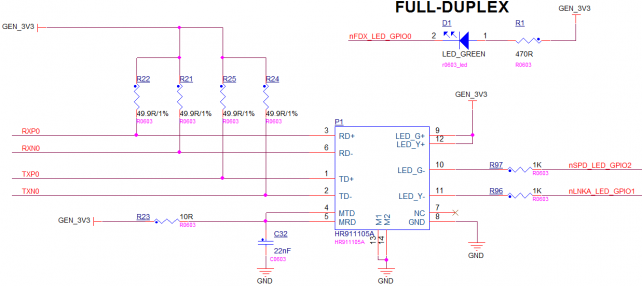
| + | 丝印(silk screen):P1<br> | ||
| + | 接口属性:USB1扩展的百兆以太网<br> | ||
| + | 引脚及信号定义如下:<br> | ||
| + | <span style="background:#CCCCCC">definition of pin & signal as below:</span><br> | ||
| + | [[文件:MY-IMX6-MB314-2.23.0.1.png|642px]]<br> | ||
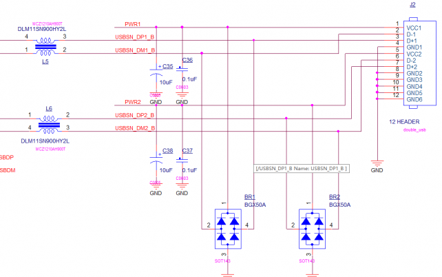
| + | == '''USB扩展(USB expansion)''' == | ||
| + | 丝印:J2<br> | ||
| + | 接口属性(interface property):USB1扩展双USB(USB1 expansion, double USB)<br> | ||
| + | 引脚及信号定义如下:<br> | ||
| + | <span style="background:#CCCCCC">definition of pin & signal as below:</span><br> | ||
| + | [[文件:MY-IMX6-MB314-2.24.0.1.png|642px]]<br> | ||
| − | == ''' | + | == '''RTC''' == |
| − | 丝印( | + | 丝印(silk screen):U8<br> |
| − | + | 接口属性(interface property):I2C通信的实时时钟(I2C communication RTC) <br> | |
| − | <span style="background:#CCCCCC"> | + | 引脚及信号定义如下:<br> |
| − | + | <span style="background:#CCCCCC">definition of pin & signal as below:</span><br> | |
| − | <span style="background:#CCCCCC">definition of pin & | + | [[文件:MY-IMX6-MB314-2.25.0.1.png|642px]]<br> |
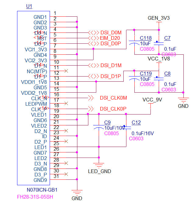
| − | [[文件: | + | == '''MIPI-DSI''' == |
| − | + | 丝印(silk screen):U1<br> | |
| + | 预选屏型号(Preselection screen type):N070ICN-GB1<br> | ||
| + | 引脚及信号定义如下:<br> | ||
| + | <span style="background:#CCCCCC">definition of pin & signal as below:</span><br> | ||
| + | [[文件:MY-IMX6-MB314-2.26.0.1.png|642px]]<br> | ||
{| class="wikitable" | {| class="wikitable" | ||
|- | |- | ||
| − | + | |引脚 (pin) | |
| − | + | |信号 (signal) | |
| − | + | |描述 (description) | |
| − | + | |引脚 (pin) | |
| + | |信号 (signal) | ||
| + | |描述 (description) | ||
|- | |- | ||
| − | | | + | |U1-1 |
| − | | | + | |GND1 |
| − | | | + | |数字地 (digital ground) |
| − | | | + | |U1-17 |
| + | |LEDPWM | ||
| + | |未连接 (unconnected) | ||
|- | |- | ||
| − | | | + | |U1-2 |
| − | | | + | |GND2 |
| − | | | + | |数字地 (digital ground) |
| − | | | + | |U1-18 |
| + | |CLK_P | ||
| + | |DSI差分时钟 (DSI differential clock) | ||
|- | |- | ||
| − | | | + | |U1-3 |
| − | | | + | |GND3 |
| − | | | + | |数字地 (digital ground) |
| − | | | + | |U1-19 |
| + | |VLED1 | ||
| + | |9V背光电压输入 (9V backlight power supply input) | ||
|- | |- | ||
| − | | | + | |U1-4 |
| − | | | + | |D0_N |
| − | | | + | |DSI差分数据0 (DSI differential data 0) |
| − | | | + | |U1-20 |
| + | |GND6 | ||
| + | |数字地 (digital ground) | ||
|- | |- | ||
| − | | | + | |U1-5 |
| − | | | + | |RST |
| − | | | + | |复位 (reset) |
| − | | | + | |U1-21 |
| − | | | + | |VLED2 |
| − | + | |9V背光电压输入 (9V backlight power supply input) | |
| − | |||
| − | |||
| − | |||
| − | |||
| − | |||
| − | |||
| − | |||
| − | |||
| − | |||
|- | |- | ||
| − | + | |U1-6 | |
| − | + | |D0_P | |
| − | + | |DSI差分数据0 (DSI differential data 0) | |
| − | + | |U1-22 | |
| + | |D2_N | ||
| + | |未连接 (unconnected) | ||
|- | |- | ||
| − | | | + | |U1-7 |
| − | | | + | |VCI1_3V3 |
| − | | | + | |3.3V输入 (3.3V input) |
| − | | | + | |U1-23 |
| + | |ID | ||
| + | |接地 (earthing) | ||
|- | |- | ||
| − | | | + | |U1-8 |
| − | | | + | |GND4 |
| − | | | + | |数字地 (digital ground) |
| − | | | + | |U1-24 |
| + | |D2_P | ||
| + | |未连接 (unconnected) | ||
|- | |- | ||
| − | | | + | |U1-9 |
| − | | | + | |VCI2_3V3 |
| − | | | + | |3.3V输入 (3.3V input) |
| − | | | + | |U1-25 |
| + | |LED1 | ||
| + | |接地 (earthing) | ||
|- | |- | ||
| − | | | + | |U1-10 |
| − | | | + | |D1_N |
| − | | | + | |DSI差分数据1 (DSI differential data 1) |
| − | | | + | |U1-26 |
| + | |GND7 | ||
| + | |数字地 (digital ground) | ||
|- | |- | ||
| − | | | + | |U1-11 |
| − | | | + | |MTP |
| − | | | + | |未连接 (unconnected) |
| − | | | + | |U1-27 |
| − | | | + | |LED2 |
| − | + | |接地 (unconnected) | |
| − | |||
| − | |||
| − | |||
| − | |||
| − | |||
| − | |||
| − | |||
| − | |||
| − | |||
|- | |- | ||
| − | + | |U1-12 | |
| − | + | |D1_P | |
| − | + | |DSI差分数据1 (DSI differential data 1) | |
| − | + | |U1-28 | |
| + | |D3_N | ||
| + | |未连接 (unconnected) | ||
|- | |- | ||
| − | | | + | |U1-13 |
| − | | | + | |VDDI2_1V8 |
| − | | | + | |1.8V输入(1.8V input) |
| − | | | + | |U1-29 |
| + | |GND8 | ||
| + | |数字地 (digital ground) | ||
|- | |- | ||
| − | | | + | |U1-14 |
| − | | | + | |GND5 |
| − | | | + | |数字地 (digital ground) |
| − | | | + | |U1-30 |
| + | |D3_P | ||
| + | |未连接 (unconnected) | ||
|- | |- | ||
| − | | | + | |U1-15 |
| − | | | + | |VDDI2_1V8 |
| − | | | + | |1.8V输入 (1.8V input) |
| − | | | + | |U1-31 |
| + | |GND9 | ||
| + | |数字地 (digital ground) | ||
|- | |- | ||
| − | | | + | |U1-16 |
| − | | | + | |CLK_N |
| − | | | + | |DSI差分时钟 (DSI differential clock) |
| − | + | | | |
| − | + | | | |
| − | + | | | |
| − | | | ||
| − | | | ||
| − | |||
| − | |||
| − | |||
| − | |||
| − | |||
| − | | | ||
|} | |} | ||
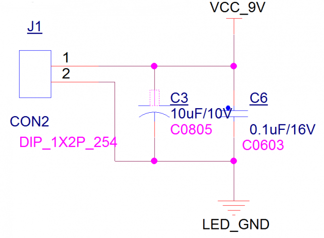
| + | == '''DSI 背光电源(DSI backlight power supply)''' == | ||
| + | 丝印(silk screen):J1<br> | ||
| + | 接口属性:9V电压输入(interface property: 9V power supply input)<br> | ||
| + | 引脚及信号定义如下:<br> | ||
| + | <span style="background:#CCCCCC">definition of pin & signal as below:</span><br> | ||
| + | [[文件:MY-IMX6-MB314-2.27.0.1.png|642px]]<br> | ||
| + | == '''主电源开关(MPS main power switch)''' == | ||
| + | 丝印(silk screen):J3<br> | ||
| + | 接口属性(interface property):电源开关(power switch)<br> | ||
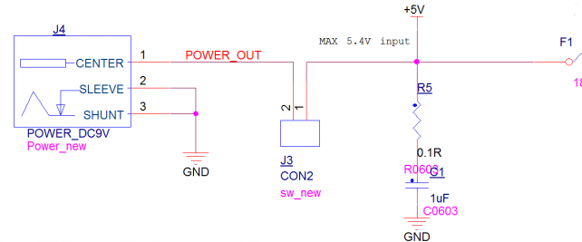
| + | == '''主电源输入(main power input)''' == | ||
| + | 丝印(silk screen):J4<br> | ||
| + | 接口属性(interface property):<br> | ||
| + | 内正外负插孔(jack with inside positive and outside negative)<br> | ||
| + | 电压(power supply):5V<br> | ||
| + | 电流(current):2.5A及以上(2.5A or above)<br> | ||
| + | 引脚及信号定义如下:<br> | ||
| + | <span style="background:#CCCCCC">definition of pin & signal as below:</span><br> | ||
| + | [[文件:MY-IMX6-MB314-2.29.0.1.png|642px]]<br> | ||
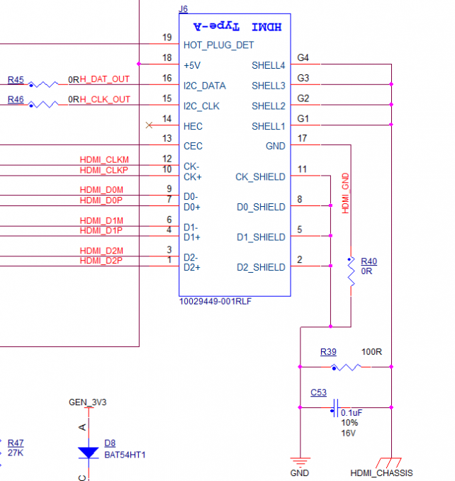
| − | == ''' | + | == '''HDMI''' == |
| − | 丝印( | + | 丝印(silk screen):J6<br> |
| − | + | 接口属性(interface property):HDMI-1.4<br> | |
| − | <span style="background:#CCCCCC">interface | + | 引脚及信号定义如下:<br> |
| − | + | <span style="background:#CCCCCC">definition of pin & signal as below:</span><br> | |
| − | <span style="background:#CCCCCC">definition of pin & | + | [[文件:MY-IMX6-MB314-2.30.0.1.png|642px]]<br> |
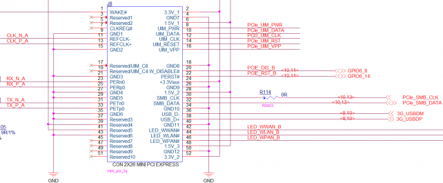
| − | [[文件: | + | == '''3G & mini-PCIE''' == |
| + | 丝印(silk screen):J8<br> | ||
| + | 接口属性(interface property):miniPCIE标准接口(miniPCIE standard interface)<br> | ||
| + | 引脚及信号定义如下:<br> | ||
| + | <span style="background:#CCCCCC">definition of pin & signal as below:</span><br> | ||
| + | [[文件:MY-IMX6-MB314-2.31.0.1.png|642px]]<br> | ||
| + | == '''JTAG''' == | ||
| + | 丝印(silk screen):U11<br> | ||
| + | 引脚及信号定义如下:<br> | ||
| + | <span style="background:#CCCCCC">definition of pin & signal as below:</span><br> | ||
| + | [[文件:MY-IMX6-MB314-2.32.0.1.png|642px]]<br> | ||
{| class="wikitable" | {| class="wikitable" | ||
|- | |- | ||
| − | + | |引脚 (pin) | |
| − | + | |信号 (signal) | |
| − | + | |描述 (description) | |
| − | + | |引脚 (pin) | |
| + | |信号 (signal) | ||
| + | |描述 (description) | ||
|- | |- | ||
| − | | | + | |U11-1 |
| − | | | + | |JTAG_TCK |
| − | | | + | |测试时钟输入(TCK input) |
| − | | | + | |U11-2 |
| + | |GND | ||
| + | |数字地 (digital ground) | ||
|- | |- | ||
| − | | | + | |U11-3 |
| − | | | + | |JTAG_TDO |
| − | | | + | |测试数据输出(test data output) |
| − | | | + | |U11-4 |
| + | |VCC | ||
| + | |3.3V输入(3.3V input) | ||
|- | |- | ||
| − | | | + | |U11-5 |
| − | | | + | |JTAG_TMS |
| − | | | + | |测试模式选择(test mode selection) |
| − | | | + | |U11-6 |
| + | |nRST | ||
| + | |复位 (reset) | ||
|- | |- | ||
| − | | | + | |U11-7 |
| − | | | + | |NC |
| − | | | + | |未连接 (unconnected) |
| − | | | + | |U11-8 |
| + | |NC | ||
| + | |未连接 (unconnected) | ||
|- | |- | ||
| − | | | + | |U11-9 |
| − | | | + | |JTAG_TDI |
| − | | | + | |测试数据输入(test mode selection) |
| − | + | |U11-10 | |
| − | |- | + | |GND |
| − | | | + | |数字地 (digital ground) |
| − | |||
| − | |||
| − | | | ||
|} | |} | ||
| − | + | == '''3G SIM卡座(3G SIM cassette)''' == | |
| − | == ''' | + | 丝印(silk screen):CON1 <br> |
| − | 丝印( | + | 接口属性:接3G SIM卡(interface property: 3G SIM card)<br> |
| − | + | 引脚及信号定义如下:<br> | |
| − | <span style="background:#CCCCCC"> | + | <span style="background:#CCCCCC">definition of pin & signal as below:</span><br> |
| − | + | [[文件:MY-IMX6-MB314-2.33.0.1.png|642px]]<br> | |
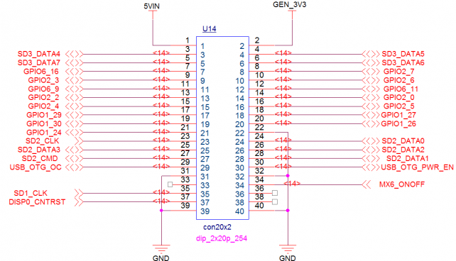
| − | + | == '''GPIO扩展(GPIO expansion)''' == | |
| − | + | 丝印(silk screen):U14<br> | |
| − | <span style="background:#CCCCCC">definition of pin & | + | 引脚及信号定义如下:<br> |
| − | [[文件: | + | <span style="background:#CCCCCC">definition of pin & signal as below:</span><br> |
| + | [[文件:MY-IMX6-MB314-2.34.0.1.png|642px]]<br> | ||
{| class="wikitable" | {| class="wikitable" | ||
|- | |- | ||
| − | + | |引脚 (pin) | |
| − | + | |信号 (signal) | |
| − | + | |描述 (description) | |
| − | + | |引脚 (pin) | |
| + | |信号 (signal) | ||
| + | |描述 (description) | ||
|- | |- | ||
| − | | | + | |U14-1 |
| − | | | + | |5VIN |
| − | | | + | |5V输入 (5V input) |
| − | | | + | |U14-2 |
| + | |GEN_3V3 | ||
| + | |3.3V输入(3.3V input) | ||
|- | |- | ||
| − | | | + | |U14-3 |
| − | | | + | |SD3_DATA4 |
| − | | | + | |可配置为GPIO(configurable as GPIO) |
| − | | | + | |U14-4 |
| + | |SD3_DATA5 | ||
| + | |可配置为GPIO(configurable as GPIO) | ||
|- | |- | ||
| − | | | + | |U14-5 |
| − | | | + | |SD3_DATA7 |
| − | | | + | |可配置为GPIO(configurable as GPIO) |
| − | | | + | |U14-6 |
| − | | | + | |SD3_DATA6 |
| − | + | |可配置为GPIO(configurable as GPIO) | |
| − | |||
| − | |||
| − | |||
| − | |||
| − | |||
| − | |||
| − | |||
| − | |||
| − | |||
|- | |- | ||
| − | + | |U14-7 | |
| − | + | |GPIO6_16 | |
| − | + | |GPIO | |
| − | + | |U14-8 | |
| + | |GPIO2_7 | ||
| + | |GPIO | ||
|- | |- | ||
| − | | | + | |U14-9 |
| − | | | + | |GPIO2_3 |
| − | | | + | |GPIO |
| − | | | + | |U14-10 |
| + | |GPIO2_6 | ||
| + | |GPIO | ||
|- | |- | ||
| − | | | + | |U14-11 |
| − | | | + | |GPIO6_9 |
| − | | | + | |GPIO |
| − | | | + | |U14-12 |
| + | |GPIO6_11 | ||
| + | |GPIO | ||
|- | |- | ||
| − | | | + | |U14-13 |
| − | | | + | |GPIO2_2 |
| − | | | + | |GPIO |
| − | | | + | |U14-14 |
| + | |GPIO2_0 | ||
| + | |GPIO | ||
|- | |- | ||
| − | | | + | |U14-15 |
| − | | | + | |GPIO2_4 |
| − | | | + | |GPIO |
| − | | | + | |U14-16 |
| + | |GPIO2_5 | ||
| + | |GPIO | ||
|- | |- | ||
| − | | | + | |U14-17 |
| − | | | + | |GPIO1_29 |
| − | | | + | |GPIO |
| − | | | + | |U14-18 |
| + | |GPIO1_27 | ||
| + | |GPIO | ||
|- | |- | ||
| − | | | + | |U14-19 |
| − | | | + | |GPIO1_30 |
| − | | | + | |GPIO |
| − | | | + | |U14-20 |
| + | |GPIO1_26 | ||
| + | |GPIO | ||
|- | |- | ||
| − | | | + | |U14-21 |
| − | | | + | |GPIO1_24 |
| − | | | + | |GPIO |
| − | | | + | |U14-22 |
| − | | | + | |GND |
| − | + | |数字地(digital ground) | |
| − | |||
| − | |||
| − | |||
| − | |||
| − | |||
| − | |||
| − | |||
| − | |||
| − | |||
|- | |- | ||
| − | + | |U14-23 | |
| − | + | |SD2_CLK | |
| − | + | |SD2时钟(SD2 clock) | |
| − | + | |U14-24 | |
| + | |SD2_DATA0 | ||
| + | |SD2数据线(SD2 data wire) | ||
|- | |- | ||
| − | | | + | |U14-25 |
| − | | | + | |SD2_DATA3 |
| − | | | + | |SD2数据线(SD2 data wire) |
| − | | | + | |U14-26 |
| + | |SD2_DATA2 | ||
| + | |SD2数据线(SD2 data wire) | ||
|- | |- | ||
| − | | | + | |U14-27 |
| − | | | + | |SD2_CMD |
| − | | | + | |SD2命令管脚(SD2 command pin) |
| − | | | + | |U14-28 |
| + | |SD2_DATA1 | ||
| + | |SD2数据线(SD2 data wire) | ||
|- | |- | ||
| − | | | + | |U14-29 |
| − | | | + | |USB_OTG_OC |
| − | | | + | |可配置为GPIO (configurable as GPIO) |
| − | | | + | |U14-30 |
| + | |USB_OTG_PWR_EN | ||
| + | |可配置为GPIO (configurable as GPIO) | ||
|- | |- | ||
| − | | | + | |U14-31 |
| − | | | + | |GND |
| − | | | + | |数字地 (digital ground) |
| − | | | + | |U14-32 |
| + | |GND | ||
| + | |数字地 (digital ground) | ||
|- | |- | ||
| − | | | + | |U14-33 |
| − | | | + | |SD1_CMD |
| − | | | + | |SD1命令管脚(SD1 command pin) |
| − | | | + | |U14-34 |
| + | |SD1_DAT0 | ||
| + | |SD1数据线 (SD1 data wire) | ||
|- | |- | ||
| − | | | + | |U14-35 |
| − | | | + | |SD1_CLK |
| − | | | + | |SD1时钟(SD1 clock) |
| − | | | + | |U14-36 |
| + | |SD1_DAT1 | ||
| + | |SD1数据线(SD1 data wire) | ||
|- | |- | ||
| − | | | + | |U14-37 |
| − | | | + | |SD1_DAT3 |
| − | | | + | |SD1数据线(SD1 data wire) |
| − | | | + | |U14-38 |
| + | |SD1_DAT2 | ||
| + | |SD1数据线(SD1 data wire) | ||
|- | |- | ||
| − | | | + | |U14-39 |
| − | |GND | + | |GND |
| − | | | + | |数字地 (digital ground) |
| − | | | + | |U14-40 |
| + | |GND | ||
| + | |数字地 (digital ground) | ||
| + | |} | ||
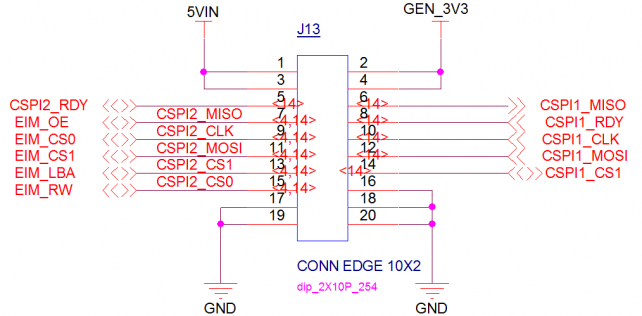
| + | |||
| + | == '''SPI扩展(SPI expansion)''' == | ||
| + | 丝印(silk screen):J13<br> | ||
| + | 引脚及信号定义如下:<br> | ||
| + | <span style="background:#CCCCCC">definition of pin & signal as below:</span><br> | ||
| + | [[文件:MY-IMX6-MB314-2.35.0.1.png|642px]]<br> | ||
| + | {| class="wikitable" | ||
|- | |- | ||
| − | | | + | |引脚 (pin) |
| − | | | + | |信号 (signal) |
| − | | | + | |描述 (description) |
| − | | | + | |引脚 (pin) |
| + | |信号 (digital ground) | ||
| + | |描述 (description) | ||
|- | |- | ||
| − | |J13- | + | |J13-1 |
| − | | | + | |5VIN |
| − | |J13- | + | |5V输入 (5V input) |
| − | | | + | |J13-2 |
| + | |5VIN | ||
| + | |5V输入 (5V input) | ||
|- | |- | ||
| − | |J13- | + | |J13-3 |
| − | | | + | |5VIN |
| − | |J13- | + | |5V输入 (5V input) |
| − | | | + | |J13-4 |
| + | |GND | ||
| + | |数字地 (digital ground) | ||
|- | |- | ||
| − | |J13- | + | |J13-5 |
| − | | | + | |CSPI2_RDY |
| − | |J13- | + | |SPI2数据信号准备 (SPI2 data-ready signal) |
| − | | | + | |J13-6 |
| + | |CSPI1_MISO | ||
| + | |SPI1主数据输入 (SPI1 Master data input) | ||
|- | |- | ||
| − | |J13- | + | |J13-7 |
| − | | | + | |CSPI2_MISO |
| − | |J13- | + | |复用EIM_OE (Reuse the EIM OE) |
| − | | | + | |J13-8 |
| + | |CSPI1_RDY | ||
| + | |SPI1数据信号准备 (SPI1 data-ready signal) | ||
|- | |- | ||
| − | |J13- | + | |J13-9 |
| − | | | + | |CSPI2_CLK |
| − | |J13- | + | |复用EIM_CS0 (Reuse the EIM_CS0 ) |
| − | | | + | |J13-10 |
| + | |CSPI1_CLK | ||
| + | |SPI1时钟 (SPI1 clock) | ||
|- | |- | ||
| − | |J13- | + | |J13-11 |
| − | | | + | |CSPI2_MOSI |
| − | |J13- | + | |复用EIM_CS1 (Reuse the EIM_CS1 ) |
| − | | | + | |J13-12 |
| + | |CSPI1_MOSI | ||
| + | |SPI1主数据输出 (SPI1 Master data output) | ||
|- | |- | ||
| − | |J13- | + | |J13-13 |
| − | | | + | |CSPI2_CS |
| − | |J13- | + | |复用EIM_LBA (Reuse the EIM_LBA ) |
| − | | | + | |J13-14 |
| + | |CSPI1_CS1 | ||
| + | |SPI1选择信号 ( selective signal ) | ||
|- | |- | ||
| − | |J13- | + | |J13-15 |
| − | | | + | |CSPI2_CS0 |
| − | |J13- | + | |复用EIM_RW (Reuse the EIM_RW) |
| − | |GND | + | |J13-16 |
| + | |GND | ||
| + | |数字地 (digital ground) | ||
|- | |- | ||
| − | |J13- | + | |J13-17 |
| − | |GND | + | |GND |
| − | |J13- | + | |数字地 (digital ground) |
| − | | | + | |J13-18 |
| + | |GND | ||
| + | |数字地 (digital ground) | ||
|- | |- | ||
| − | |J13- | + | |J13-19 |
| − | |GND | + | |GND |
| − | | | + | |数字地 (digital ground) |
| − | + | |J13-20 | |
| − | + | |GND | |
| − | + | |数字地 (digital ground) | |
| − | |||
| − | |||
| − | |||
| − | |||
| − | |||
| − | |||
| − | |J13- | ||
| − | |||
| − | |||
| − | |||
| − | |GND | ||
| − | | | ||
| − | |||
| − | |||
| − | |||
| − | |||
| − | |||
| − | |||
| − | |||
| − | |||
| − | |||
| − | |||
| − | |||
| − | |||
| − | |||
| − | |||
| − | |||
| − | |||
| − | |||
| − | |||
| − | |||
| − | |||
| − | |||
|} | |} | ||
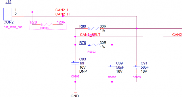
| − | + | == '''CAN2''' == | |
| − | == ''' | + | 丝印(silk screen):J15<br> |
| − | 丝印( | + | 接口属性(interface property):CAN2<br> |
| − | + | 引脚及信号定义如下:<br> | |
| − | <span style="background:#CCCCCC"> | + | <span style="background:#CCCCCC">definition of pin & signal as below:</span><br> |
| − | [[文件: | + | [[文件:MY-IMX6-MB314-2.36.0.1.png|642px]]<br> |
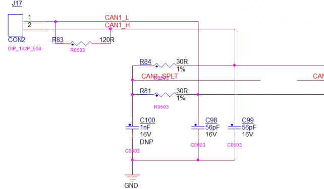
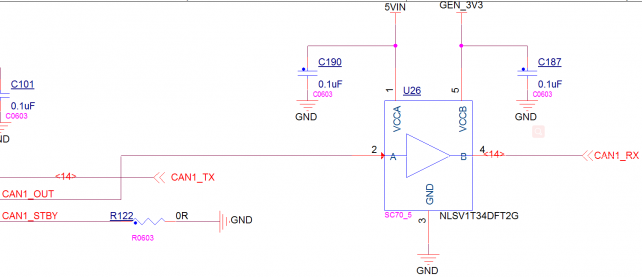
| − | + | == '''CAN1''' == | |
| − | + | 丝印(silk screen):J17<br> | |
| − | == ''' | + | 接口属性(interface property):CAN1<br> |
| − | 丝印( | + | 引脚及信号定义如下:<br> |
| − | + | <span style="background:#CCCCCC">definition of pin & signal as below:</span><br> | |
| − | <span style="background:#CCCCCC"> | + | [[文件:MY-IMX6-MB314-2.37.0.1.png|642px]]<br> |
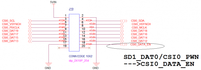
| − | + | == '''CSI(CMOS Sensor Interface)''' == | |
| − | <span style="background:#CCCCCC">definition of pin & | + | 丝印(interface property):J19<br> |
| − | [[文件: | + | 引脚及信号定义如下:<br> |
| + | <span style="background:#CCCCCC">definition of pin & signal as below:</span><br> | ||
| + | [[文件:MY-IMX6-MB314-2.38.0.1.png|642px]]<br> | ||
{| class="wikitable" | {| class="wikitable" | ||
|- | |- | ||
| − | + | |引脚 (pin) | |
| − | + | |信号 (signal) | |
| − | + | |描述 (description) | |
| − | + | |引脚 (pin) | |
| + | |信号 (signal) | ||
| + | |描述 (description) | ||
|- | |- | ||
| − | | | + | |J19-1 |
| − | | | + | |5VIN |
| − | | | + | |5V输入 (5V input) |
| − | | | + | |J19-2 |
| + | |GND | ||
| + | |数字地 (digital ground) | ||
|- | |- | ||
| − | | | + | |J19-3 |
| − | | | + | |CSI0_SCL |
| − | | | + | |I2C1时钟(I2C1 clock) |
| − | | | + | |J19-4 |
| + | |CSI0_SDA | ||
| + | |I2C1数据(I2C1 data) | ||
|- | |- | ||
| − | | | + | |J19-5 |
| − | | | + | |CSI0_VSYNCH |
| − | | | + | |场同步接口(field synchronization interface) |
| − | | | + | |J19-6 |
| + | |CSI0_HSYNCH | ||
| + | |行同步接口(Line synchronization interface) | ||
|- | |- | ||
| − | | | + | |J19-7 |
| − | | | + | |CDI0_PIXCLK |
| − | | | + | |摄像头输出主时钟(camera output master clock) |
| − | | | + | |J19-8 |
| + | |CSI0_MCLK | ||
| + | |CSI输出主时钟(CSI output master clock) | ||
|- | |- | ||
| − | | | + | |J19-9 |
| − | | | + | |CSI0_DAT19 |
| − | | | + | |CSI数据总线 (CSI data bus) |
| − | | | + | |J19-10 |
| + | |CSI0_DAT18 | ||
| + | |CSI数据总线(CSI data bus) | ||
|- | |- | ||
| − | | | + | |J19-11 |
| − | | | + | |CSI0_DAT17 |
| − | | | + | |CSI数据总线 (CSI data bus) |
| − | | | + | |J19-12 |
| + | |CSI0_DAT16 | ||
| + | |CSI数据总线(CSI data bus) | ||
|- | |- | ||
| − | | | + | |J19-13 |
| − | | | + | |CSI0_DAT15 |
| − | | | + | |CSI数据总线 (CSI data bus) |
| − | | | + | |J19-14 |
| + | |CSI0_DAT14 | ||
| + | |CSI数据总线(CSI data bus) | ||
|- | |- | ||
| − | | | + | |J19-15 |
| − | | | + | |CSI0_DAT13 |
| − | | | + | |CSI数据总线 (CSI data bus) |
| − | | | + | |J19-16 |
| + | |CSI0_DAT12 | ||
| + | |CSI数据总线(CSI data bus) | ||
|- | |- | ||
| − | | | + | |J19-17 |
| − | |GND | + | |GND |
| − | | | + | |数字地 (digital ground) |
| − | + | |J19-18 | |
| − | + | |CSI0_DATA_EN | |
| − | + | |总线使能(bus enable) | |
| − | |||
| − | |||
| − | |||
| − | |||
| − | |||
| − | |||
| − | |||
| − | |||
| − | |||
| − | |||
| − | |||
| − | |||
| − | |||
| − | |||
| − | |||
| − | |||
| − | |||
| − | |||
| − | |||
| − | |||
| − | |||
| − | |||
| − | |||
| − | |||
| − | |||
| − | |||
| − | |||
| − | |||
| − | |||
| − | |||
| − | |||
| − | |||
|- | |- | ||
| − | + | |J19-19 | |
| − | + | |NC | |
| − | + | |未连接 (unconnected) | |
| − | + | |J19-20 | |
| − | |- | + | |NC |
| − | | | + | |未连接 (unconnected) |
| − | | | ||
| − | | | ||
| − | | | ||
| − | | | ||
| − | |||
| − | |||
| − | |||
| − | |||
|} | |} | ||
| − | |||
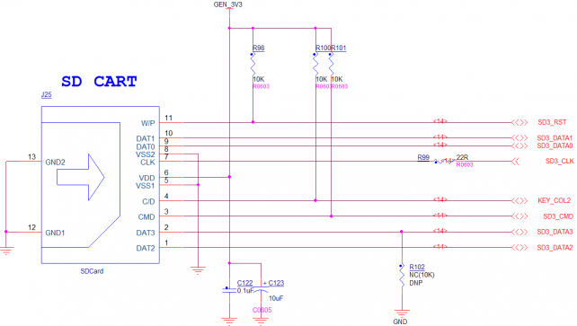
| − | == ''' | + | == '''SD卡座(SD cassette) ''' == |
| − | + | 丝印(silk screen):J25<br> | |
| − | + | 接口属性:标准SD卡座(interface property: standard SD cassette) <br> | |
| − | + | 引脚及信号定义如下:<br> | |
| − | + | <span style="background:#CCCCCC">definition of pin & signal as below:</span><br> | |
| − | + | [[文件:MY-IMX6-MB314-2.39.0.1.png|642px]]<br> | |
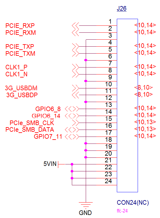
| − | + | == '''PCIE扩展(PCIT expansion)''' == | |
| − | + | 丝印(silk screen):J26<br> | |
| − | 丝印( | + | 引脚及信号定义如下:<br> |
| − | + | <span style="background:#CCCCCC">definition of pin & signal as below:</span><br> | |
| − | + | [[文件:MY-IMX6-MB314-2.40.0.1.png|642px]]<br> | |
| − | |||
| − | |||
| − | |||
| − | |||
| − | |||
| − | |||
| − | <span style="background:#CCCCCC"> | ||
| − | [[文件: | ||
| − | |||
| − | |||
| − | |||
| − | |||
| − | |||
| − | |||
| − | |||
| − | |||
| − | |||
| − | == ''' | ||
| − | |||
| − | |||
| − | |||
| − | |||
| − | |||
| − | |||
| − | |||
| − | 丝印( | ||
| − | |||
| − | |||
| − | |||
| − | <span style="background:#CCCCCC">definition of pin & | ||
| − | [[文件: | ||
{| class="wikitable" | {| class="wikitable" | ||
|- | |- | ||
| − | + | |引脚 (pin) | |
| − | + | |信号 (signal) | |
| − | + | |描述 (description) | |
| − | + | |引脚 (pin) | |
| + | |信号 (signal) | ||
| + | |描述 (description) | ||
|- | |- | ||
| − | | | + | |J26-1 |
| − | | | + | |PCIE_RXP |
| − | | | + | |接收差分信号(receiving differential signal) |
| − | | | + | |J26-13 |
| + | |GPIO6_8 | ||
| + | |GPIO | ||
|- | |- | ||
| − | | | + | |J26-2 |
| − | | | + | |PCIE_RXM |
| − | | | + | |接收差分信号(receiving differential signal) |
| − | | | + | |J26-14 |
| + | |GPIO6_14 | ||
| + | |GPIO | ||
|- | |- | ||
| − | | | + | |J26-3 |
| − | | | + | |GND |
| − | | | + | |数字地 (digital ground) |
| − | | | + | |J26-15 |
| + | |PCIE_SMD_CLK | ||
| + | |I2C3时钟 (I2C3 clock) | ||
|- | |- | ||
| − | | | + | |J26-4 |
| − | | | + | |PCIE_TXP |
| − | | | + | |发送差分信号(sending differential signal) |
| − | | | + | |J26-16 |
| + | |PCIE_SMB_DATA | ||
| + | |I2C3数据(I2C3 data) | ||
|- | |- | ||
| − | | | + | |J26-5 |
| − | | | + | |PCIE_TXM |
| − | | | + | |发送差分信号(sending differential signal |
| − | | | + | |J26-17 |
| + | |GPIO7_11 | ||
| + | |GPIO | ||
|- | |- | ||
| − | | | + | |J26-6 |
| − | | | + | |GND |
| − | | | + | |数字地 (digital ground) |
| − | | | + | |J26-18 |
| + | |GND | ||
| + | |数字地 (digital ground) | ||
|- | |- | ||
| − | | | + | |J26-7 |
| − | | | + | |CLK1_P |
| − | | | + | |差分时钟(differential clock) |
| − | | | + | |J26-19 |
| + | |GND | ||
| + | |数字地 (digital ground) | ||
|- | |- | ||
| − | | | + | |J26-8 |
| − | | | + | |CLK1_N |
| − | | | + | |差分时钟(differential clock) |
| − | | | + | |J26-20 |
| + | |GND | ||
| + | |数字地(digital ground) | ||
|- | |- | ||
| − | | | + | |J26-9 |
| − | | | + | |GND |
| − | | | + | |数字地 (digital ground) |
| − | | | + | |J26-21 |
| + | |5VIN | ||
| + | |5V输入 (5V input) | ||
|- | |- | ||
| − | | | + | |J26-10 |
| − | | | + | |3G_USBDM |
| − | | | + | |USB差分信号(USB differential signal) |
| − | | | + | |J26-22 |
| + | |5VIN | ||
| + | |5V输入(5V input) | ||
|- | |- | ||
| − | | | + | |J26-11 |
| − | | | + | |3G_USBDP |
| − | | | + | |USB差分信号(USB differential signal) |
| − | | | + | |J26-23 |
| + | |5VIN | ||
| + | |5V输入(5V input) | ||
|- | |- | ||
| − | | | + | |J26-12 |
| − | | | + | |GND |
| − | | | + | |数字地 (digital ground) |
| − | | | + | |J26-24 |
| + | |5VIN | ||
| + | |5V输入(5V input) | ||
| + | |} | ||
| + | |||
| + | == '''WIFI模块(WIFI module)''' == | ||
| + | 丝印(silk screen):U24<br> | ||
| + | 模块型号(module model):UM12BS<br> | ||
| + | 引脚及信号定义如下:<br> | ||
| + | <span style="background:#CCCCCC">definition of pin & signal as below:</span><br> | ||
| + | [[文件:MY-IMX6-MB314-2.41.0.1.png|642px]]<br> | ||
| + | == '''GPS模块(GPS module)''' == | ||
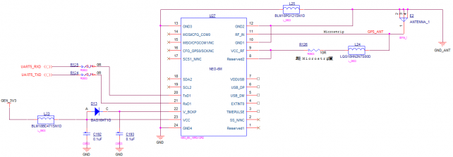
| + | 丝印(silk screen):U27<br> | ||
| + | 模块型号(module model):NEO-6M<br> | ||
| + | 引脚及信号定义如下:<br> | ||
| + | <span style="background:#CCCCCC">definition of pin & signal as below:</span><br> | ||
| + | [[文件:MY-IMX6-MB314-2.42.0.1.png|642px]]<br> | ||
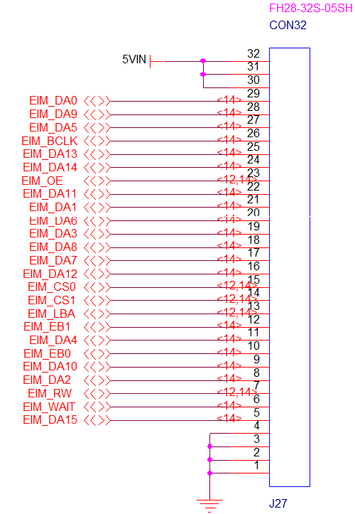
| + | == '''EIM扩展(EIM expansion)''' == | ||
| + | 丝印(silk screen):J27<br> | ||
| + | 引脚及信号定义如下:<br> | ||
| + | <span style="background:#CCCCCC">definition of pin & signal as below:</span><br> | ||
| + | [[文件:MY-IMX6-MB314-2.43.0.1.png|642px]]<br> | ||
| + | {| class="wikitable" | ||
|- | |- | ||
| − | | | + | |引脚 (pin) |
| − | | | + | |信号 (signal) |
| − | | | + | |描述 (description) |
| − | | | + | |引脚 (pin) |
| + | |信号 (signal) | ||
| + | |描述(description) | ||
|- | |- | ||
| − | | | + | |J27-1 |
| − | | | + | |GND |
| − | | | + | |数字地(digital ground) |
| − | | | + | |J27-17 |
| + | |EIM_DA7 | ||
| + | |地址&数据(address & data) | ||
|- | |- | ||
| − | | | + | |J27-2 |
| − | | | + | |GND |
| − | | | + | |数字地(digital ground) |
| − | | | + | |J27-18 |
| + | |EIM_DA8 | ||
| + | |地址&数据(address & data) | ||
|- | |- | ||
| − | | | + | |J27-3 |
| − | | | + | |GND |
| − | | | + | |数字地(digital ground) |
| − | | | + | |J27-19 |
| + | |EIM_DA3 | ||
| + | |地址&数据(address & data) | ||
|- | |- | ||
| − | | | + | |J27-4 |
| − | | | + | |GND |
| − | | | + | |数字地(digital ground) |
| − | | | + | |J27-20 |
| + | |EIM_DA6 | ||
| + | |地址&数据(address & data) | ||
|- | |- | ||
| − | | | + | |J27-5 |
| − | | | + | |EIM_DA15 |
| − | | | + | |地址&数据 (address & data) |
| − | | | + | |J27-21 |
| + | |EIM_DA1 | ||
| + | |地址&数据 (address & data) | ||
|- | |- | ||
| − | | | + | |J27-6 |
| − | | | + | |EIM_WAIT |
| − | | | + | | |
| − | | | + | |J27-22 |
| + | |EIM_DA11 | ||
| + | |地址&数据 (address & data) | ||
|- | |- | ||
| − | | | + | |J27-7 |
| − | | | + | |EIM_EW |
| − | | | + | | |
| − | + | |J27-23 | |
| − | + | |EIM_OE | |
| − | + | | | |
| − | |||
| − | | | ||
| − | | | ||
| − | |||
| − | |||
| − | |||
| − | |||
| − | |||
| − | |||
| − | |||
| − | |||
| − | |||
| − | | | ||
|- | |- | ||
| − | | | + | |J27-8 |
| − | | | + | |EIM_DA2 |
| − | | | + | |地址&数据(address & data) |
| − | | | + | |J27-24 |
| + | |EIM_DA14 | ||
| + | |地址&数据(address & data) | ||
|- | |- | ||
| − | | | + | |J27-9 |
| − | | | + | |EIM_DA10 |
| − | | | + | |地址&数据(address & data) |
| − | | | + | |J27-25 |
| + | |EIM_DA13 | ||
| + | |地址&数据(address & data) | ||
|- | |- | ||
| − | | | + | |J27-10 |
| − | | | + | |EIM_EB0 |
| − | | | + | | |
| − | + | |J27-26 | |
| − | + | |EIM_BCLK | |
| − | + | |输出时钟( output clock) | |
| − | |||
| − | |||
| − | |||
| − | |||
| − | | | ||
| − | | | ||
| − | | | ||
| − | |||
| − | |||
| − | |||
| − | |||
| − | |||
| − | |||
| − | |||
| − | |||
| − | |||
| − | |||
| − | |||
| − | |||
|- | |- | ||
| − | + | |J27-11 | |
| − | + | |EIM_DA4 | |
| − | + | |地址&数据(address & data) | |
| − | + | |J27-27 | |
| − | + | |EIM_DA5 | |
| − | + | |地址&数据(address & data) | |
|- | |- | ||
| − | | | + | |J27-12 |
| − | | | + | |EIM_CS1 |
| − | | | + | | |
| − | | | + | |J27-28 |
| − | | | + | |EIM_DA9 |
| − | | | + | |地址&数据(address & data) |
|- | |- | ||
| − | | | + | |J27-13 |
| − | | | + | |EIM_LBA |
| − | | | + | | |
| − | | | + | |J27-29 |
| − | | | + | |EIM_DA0 |
| − | | | + | |地址&数据 |
|- | |- | ||
| − | | | + | |J27-14 |
| − | | | + | |EIM_CS1 |
| − | | | + | |片选1(chip select 1) |
| − | | | + | |J27-30 |
| − | | | + | |5VIN |
| − | | | + | |5V输入 (5V input) |
|- | |- | ||
| − | | | + | |J27-15 |
| − | | | + | |EIM_CS0 |
| − | | | + | |片选1(chip select 0) |
| − | | | + | |J27-31 |
| − | | | + | |5VIN |
| − | | | + | |5V输入 (5V input) |
|- | |- | ||
| − | | | + | |J27-16 |
| − | | | + | |EIM_DA12 |
| − | | | + | |地址&数据(address & data) |
| − | | | + | |J27-1 |
| − | | | + | |5VIN |
| − | | | + | |5V输入 (5V input) |
|} | |} | ||
| − | |||
| − | |||
| − | |||
| − | |||
| − | |||
| − | |||
| − | |||
| − | |||
| − | |||
| − | |||
| − | |||
| − | |||
| − | |||
| − | |||
2018年6月8日 (五) 11:47的版本
目录
- 1 = 接口概览(overview of interfaces) =
- 2 正面图(MB314 + CB314)(front view(MB314+CB314)
- 3 正面图(MB314 + CB336)(front view(MB314+CB336)
- 4 背面图(MB314)(rear view(MB314))
- 5 = 接口功能(interface function) =
- 6 两位拨码开关(2 bit dial switch)
- 7 音量减(volume down)
- 8 音量加(volume up)
- 9 唤醒(wake up)
- 10 复位(reset)
- 11 18/24bit LVDS0
- 12 18/24bit RGB
- 13 18/24bit LVDS1
- 14 I2C扩展(I2C expansion)
- 15 18/24bit LVDS1扩展(18/24bit LVDS1 expansion)
- 16 GPS天线座(GPS antenna pedestal)
- 17 调试串口(debug serial port)
- 18 耳机输出(headphone output)
- 19 麦克风输入(MIC)
- 20 串口扩展/TTL电平(serial port extension/TTL electrical level)
- 21 232串口(232 serial port)
- 22 485串口(485 serial port)
- 23 RGMII
- 24 SATA II
- 25 SATA电源(SATA power supply)
- 26 MIPI-CSI
- 27 OTG
- 28 RMII
- 29 USB扩展(USB expansion)
- 30 RTC
- 31 MIPI-DSI
- 32 DSI 背光电源(DSI backlight power supply)
- 33 主电源开关(MPS main power switch)
- 34 主电源输入(main power input)
- 35 HDMI
- 36 3G & mini-PCIE
- 37 JTAG
- 38 3G SIM卡座(3G SIM cassette)
- 39 GPIO扩展(GPIO expansion)
- 40 SPI扩展(SPI expansion)
- 41 CAN2
- 42 CAN1
- 43 CSI(CMOS Sensor Interface)
- 44 SD卡座(SD cassette)
- 45 PCIE扩展(PCIT expansion)
- 46 WIFI模块(WIFI module)
- 47 GPS模块(GPS module)
- 48 EIM扩展(EIM expansion)
= 接口概览(overview of interfaces) =
正面图(MB314 + CB314)(front view(MB314+CB314)
正面图(MB314 + CB336)(front view(MB314+CB336)
背面图(MB314)(rear view(MB314))
= 接口功能(interface function) =
两位拨码开关(2 bit dial switch)
丝印(silk screen):SW1
引脚及信号定义如下:
definition of pin & signal as below:
