“MYZR-IMX6-MB200 Hardware Introduction”的版本间的差异
(创建页面,内容为“<div> = '''overview of interfaces''' = ---- == '''Front view''' == 647px == '''Rear view''' == File:myimx6ek200_rear view.jpg|642...”) |
小 (Admin移动页面MY-IMX6-MB200 Hardware Introduction至MYZR-IMX6-MB200 Hardware Introduction,不留重定向) |
(没有差异)
| |
2020年10月22日 (四) 14:03的最新版本
目录
- 1 overview of interfaces
- 2 Interface function
- 2.1 18/24bit LVDS0
- 2.2 18/24bit RGB
- 2.3 18/24bit LVDS1
- 2.4 10M/100M Ethernet-1
- 2.5 Earphone output
- 2.6 Microphone input
- 2.7 HDMI
- 2.8 SATA power supply
- 2.9 OTG
- 2.10 SATA II
- 2.11 10M/100M Ethernet-2
- 2.12 USB expansion
- 2.13 Debug uart
- 2.14 Main power supply switch
- 2.15 Main power supply switch
- 2.16 Reset
- 2.17 Wake up
- 2.18 Volume up
- 2.19 Volume down
- 2.20 RS-232 serial port
- 2.21 RS-485 serial port
- 2.22 MINI-PCIE
- 2.23 Serial port expansion/TTL electrical level
- 2.24 GPIO/SD2
- 2.25 SPI expansion
- 2.26 SIM cassette
- 2.27 MIPI-CSI
- 2.28 CMOS-CSI
- 2.29 CAN2
- 2.30 CAN1
- 2.31 I2C expansion
- 2.32 GPS antenna pedestal
- 2.33 GPS
- 2.34 MINI_PCIE_FPC
- 2.35 SD3
- 2.36 WIFI
- 2.37 RTC
- 2.38 RTC_Batter
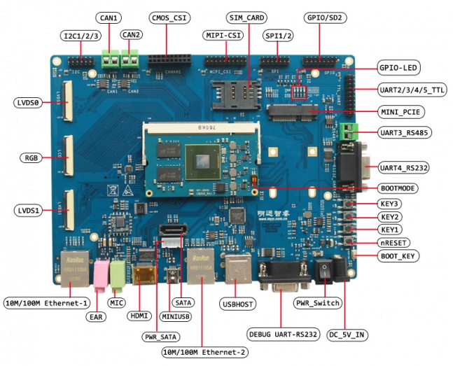
overview of interfaces
Front view
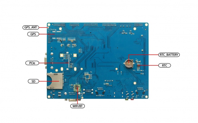
Rear view
Interface function
18/24bit LVDS0
- Silk screen:J24
- LVDS0 crystal liquid is 24 bit mode,compatible with 18bit mode,through which LVDS resistance screen panel and LVDS capacitor screen panel in different sizes and specifications produced by MYZR can be cnnected。LVDS0 interface block is build with connector imported,abandon the cheap drawer type produced domestically,which is opposite press type to ensure easier installation,better performance and connectivity.
- Definition of pin & signal as below
| Pin | Singnal | Description |
|---|---|---|
| J24-16 | SD1_DAT1/TOUCH_nEINT1 | GPIO control |
| J24-17 | NANDF_CS3 | GPIO control |
| J24-19 | DISP0_CONTRAST | LVDS0 backlight adjustment |
| J24-21 | TOUCH_SCL | I2C clock |
| J24-22 | TOUCH_SDA | I2C data |
18/24bit RGB
- Silkscreen:J23
- RGB crystal liquid is 24bit mode,compatible to 18bit/16bit mode,through which RGB resistance screen panel and RGB capacitor screen panel in different sizes and specifications produced by MYZR can be cnnected,RGB interface block is build with connector imported,abandon the cheap drawer type produced domestically,which is opposite press type to ensure easier installation,better performance and connectivity。</span>
- Definition of pin & signal:
| Pin | Singnal | Description |
|---|---|---|
| J23-31 | SD1_DAT1/TOUCH_nEINT1 | GPIO control |
| J23-30 | NANDF_CS3 | GPIO control |
| J23-19 | DISP0_CONTRAST | LVDS0 backlight adjustment |
| J23-32 | TOUCH_SCL | I2C clock |
| J23-33 | TOUCH_SDA | I2C data |
18/24bit LVDS1
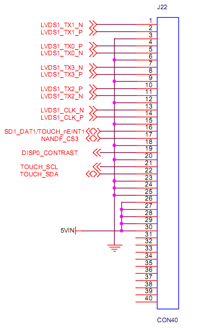
- Silk screen:J22
- LVDS1 crystal liquid interface is the same as LVDS0 in terms of definition and connector model,users can connect crytal liquid in LVDS0 directly to LVDS1.
- Definition of pin & signal:
| Pin | Singnal | Description |
|---|---|---|
| J22-16 | SD1_DAT1/TOUCH_nEINT1 | GPIO control |
| J22-17 | NANDF_CS3 | GPIO control |
| J22-19 | DISP0_CONTRAST | LVDS0 backlight adjustment |
| J22-21 | TOUCH_SCL | I2C clock |
| J22-22 | TOUCH_SDA | I2C data |
10M/100M Ethernet-1
Silk screen:P4
Interface property:100 - Mbps Ethernet standard interface
Earphone output
Silk screen:J20
Interface property:audio signal output,3.5mm interface
Microphone input
Silk screen:J18
Interface propoerty:audio signal input,3.5mm interface
HDMI
Silk screen:J5
Interface property:HDMI-1.4 standard interface
SATA power supply
silk screen:J12
Definition of pin & signal:
| pin | signal | description |
|---|---|---|
| J12-1 | 5VIN | 5V power input |
| J12-2 | GND | digital |
| J12-3 | GND | digital |
| J12-4 | NC | unconnected |
OTG
silk screen:J5
Interface property:USB ON-The-GO,for burn and write
SATA II
Silk screen:J11
Interface property:3Gbps SATA II standard interface
10M/100M Ethernet-2
Silk screen:P3
Interface property:100 - Mbps Ethernet standard interface
USB expansion
silk screen:J8
Interface property:USB1 expanded to dual USB,standard USB interface
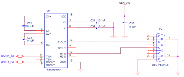
Debug uart
Silk screen:P2
Interface property:3 thread standard RS232 port,for debug of sirial port
Main power supply switch
Silk screen:J3
Interface property:power supply switch
Status property:—,close;O,off
Main power supply switch
Silk screen:J4
Interface property:
- Jack with inside positive and outside negative
- Voltage:5V
- Current:2.5A and above
- Jack with inside positive and outside negative
Reset
Silk screen:SW1
Function:reset
Wake up
Silk screen:SW2
Interface property:sleeping wake up
Volume up
Silk screen:SW3
Interface property:volume control(volume up)
Volume down
Silk screen:SW2
Interface property:volume control(volume down)
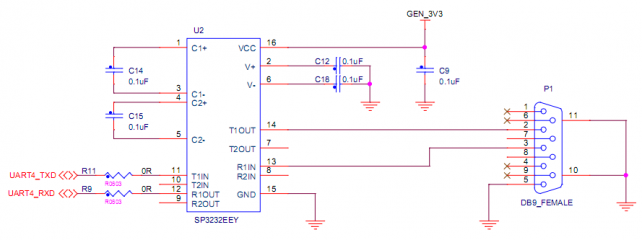
RS-232 serial port
silk screen:P1
Interface property:UART4,3 thread standard RS232 port
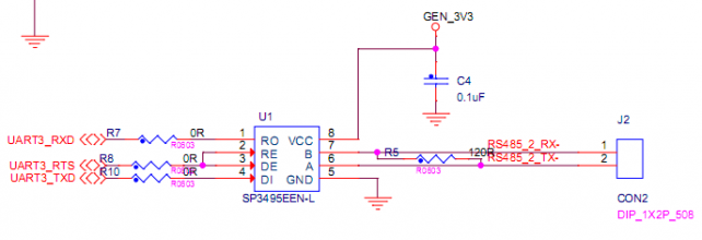
RS-485 serial port
Silk screen:J2
Interface property:UART3,RS-485 serial port
MINI-PCIE
Silk screen:J6
Interface property:standard MINI-PCIE port
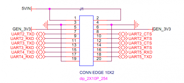
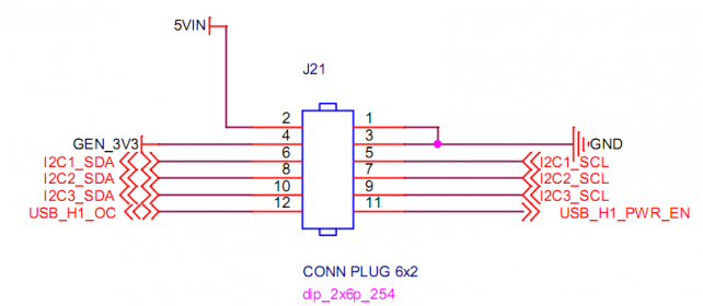
Serial port expansion/TTL electrical level
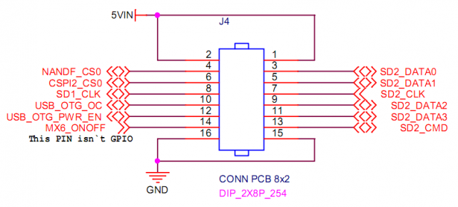
GPIO/SD2
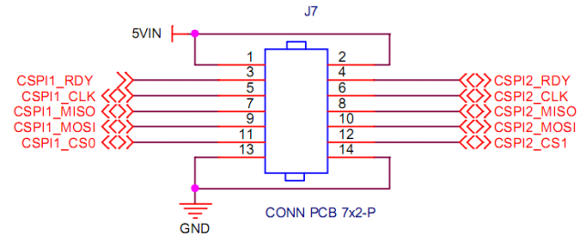
SPI expansion
SIM cassette
Silk screen:CON1
Interface property:standard SIM cassette
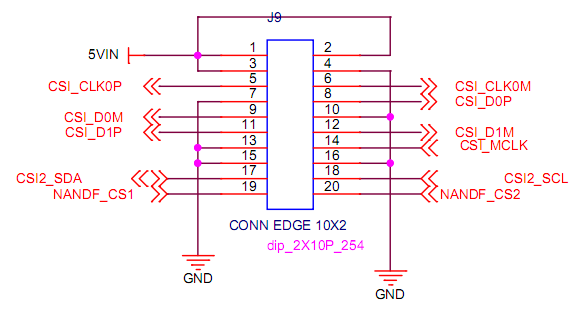
MIPI-CSI
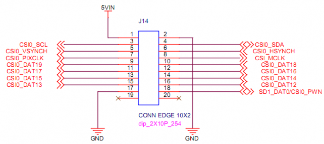
CMOS-CSI
CAN2
Silk screen:J16
Interface property:CAN2

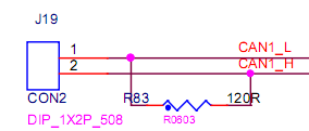
CAN1
Silk screen:J19
Interface property:CAN1
I2C expansion
GPS antenna pedestal
Silk screen:E4
Interface property:antenna pedestal
GPS
Silk screen:U15
Module model:NEO-6M
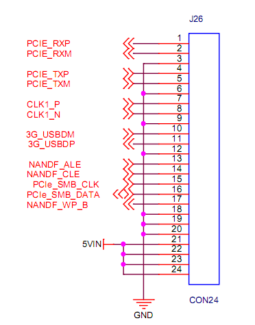
MINI_PCIE_FPC
Silk screen:J26
Note:can't be used with MINI_PCIE simultaneously,e.g can only choose one from the two.
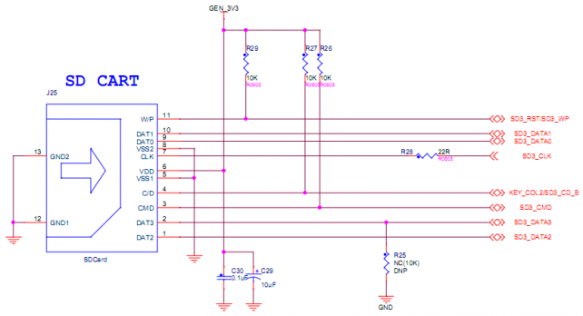
SD3
Silk screen:J25
Interface property:standard SD cassette
WIFI
Silk screen:U16
Module model:UM12BS

RTC
Silk screen:U19
Interface property:real clock for I2C communication
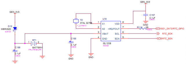
RTC_Batter
Silk screen:BT1
