MYZR-IMX6-EK140P Linux-4.1.15 Test Manual
目录
Test of network interface
- Interface property:
| Evaluation board model | CPU interface | System interface | Interface silk screen |
| MY-IMX6-EK140 | ENET1 | eth0 | P10 |
| MY-IMX6-EK140 | ENET1 | eth1 | P8 |
Test method
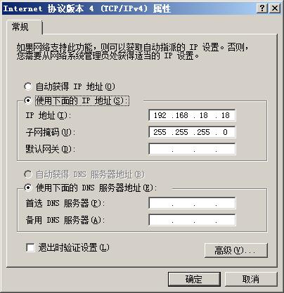
1)Configure computer IP
Set IP of cable network interface card for computer as 192.168.18.18

2) Eth0 test for Wth0 connection
- Lan line connection:connect interface corresponding to “eth0”on evaluation board with interface of cable network interface card on computer through lan line.
- Set IP for evaluation board:
- # ifconfig eth0 192.168.18.36 ::# configure the eth0
- # ifconfig eth0 192.168.18.36 ::# configure the eth0
- Execute test command:
- # ping 192.168.18.18 -c 2 -w 4 ::# send ICMP to HOST
- # ping 192.168.18.18 -c 2 -w 4 ::# send ICMP to HOST
- View test result,you can see information outputed by system like below:
- --- 192.168.18.18 ping statistics ---
- 2packets transmitted, 2 packets received, 0% packet loss
- --- 192.168.18.18 ping statistics ---
- Test reuslt:“0% packet loss” represent passing of test
Figures

3)eth1 test is the same as eth0
USB test
- Interface property:
| Evaluation board model | CPU interface | System interface | Interface silk screen |
| MY-IMX6-EK140 | USB_OTG1 | USB OTG | P18 |
| USB_OTG2 | USB HOST | P20 |
===USB OTG test===
1)Connect to USB1 with USB switch wiring from MicroUSB,system will output information like below:
- ci_hdrc ci_hdrc.0: new USB bus registered, assigned bus number 2
- ci_hdrc ci_hdrc.0: USB 2.0 started, EHCI 1.00
- ci_hdrc ci_hdrc.0: new USB bus registered, assigned bus number 2
2)Connect USB device,e.g insert U disk to USD port on the switch wiring,system will output information like below:
- usb 2-1: new high-speed USB device number 12 using ci_hdrc
- usb-storage 2-1:1.0: USB Mass Storage device detected
- usb 2-1: new high-speed USB device number 12 using ci_hdrc
3)Take out USB device,system will output information like below:
- usb 2-1: USB disconnect, device number 12
- usb 2-1: USB disconnect, device number 12
4)Take out USB switch wiring,system will output information like below.
- ci_hdrc ci_hdrc.0: remove, state 4
- usb usb2: USB disconnect, device number 1
- ci_hdrc ci_hdrc.0: USB bus 2 deregistered
- ci_hdrc ci_hdrc.0: remove, state 4
USB HOST test
1)MY-IMX6-EK140 USB HOST is socket type,if need to test the function of HOST,need to connect signal line of USB HOST to the USB head self-prepared,?the operation need an assistance from hardware engineer.
2)Moreover,please let engineer know that power supply capability of CPU的USB_VBUS is not enough,so need to connect“5V_core”with USB_VBUS
Figure


![]()

SD card test
- Interface property:
| Evaluation board model | CPU interface | System interface | Interface silk screen |
| MY-IMX6-EK140 | SD1 | mmc0 | U15 |
Test instruction
MY-IMX6-EK140 TF card interface doesn't support hot plug
Test method
1)Power off MY-IMX6-EK140
2)Install TF card in TF card holder,and confirm the installation ok
3)Power on MY-IMX6-EK140,enter the system after booting is finished
5)Check TF card
- # dmesg | grep "mmc0"
- # dmesg | grep "mmc0"
If IF card is normal, then you can see information like below:
- mmc0: host does not support reading read-only switch. assuming write-enable.
- mmc0: new high speed SD card at address 0002
- mmc0: host does not support reading read-only switch. assuming write-enable.
Standard GPIO test
- Interface property:
| Evaluation board model | CPU interface | System device | Signal Name | Interface position |
| MY-IMX6-EK140 | SNVS_TAMPER1 | gpio129 | SNVS_TAMPER1 | P21:16 |
Test instruction
Take GPIO129 as an example of standard GPIO test,other GPIO tests refer to the test method of GPIO129
Test method
1)Set IO order number of GPIO which need to be tested
- # OUT_IO_NUMBER=129
- # OUT_IO_NUMBER=129
2)Lead out GPIO
- # echo ${OUT_IO_NUMBER} > /sys/class/gpio/export
- # echo ${OUT_IO_NUMBER} > /sys/class/gpio/export
3)Set direction for GPIO
- # echo "out" > /sys/class/gpio/gpio${OUT_IO_NUMBER}/direction
- # echo "out" > /sys/class/gpio/gpio${OUT_IO_NUMBER}/direction
4)Control output electrical level
- # echo 0 > /sys/class/gpio/gpio${OUT_IO_NUMBER}/value
- # echo 0 > /sys/class/gpio/gpio${OUT_IO_NUMBER}/value
Leads detected by multimeter accordingly will be low electrical level after execution of command
- # echo 1 > /sys/class/gpio/gpio${OUT_IO_NUMBER}/value
- # echo 1 > /sys/class/gpio/gpio${OUT_IO_NUMBER}/value
Leads detected by multimeter accordingly will be high electrical level after execution of command
Serial port test
Test instruction
Serial port self - collection test was used.
- Serial port property:
| Evaluation board model | UARTx | TX | RX | System interface |
| MY-IMX6-EK140P | UART3 | P21:26 | P21:25 | ttymxc2 |
| UART2 | P21:28 | P21:27 | ttymxc1 |
Tip: only the transceiver pins of the test serial port are listed here. See the schematic diagram for the definition of other pins of the serial port.
Test method
(1)Enter the test program directory
- # cd /home/root/my-demo/linux-4.1.15/
- # cd /home/root/my-demo/linux-4.1.15/
(2)Short the 26 and 25 pins of P21.
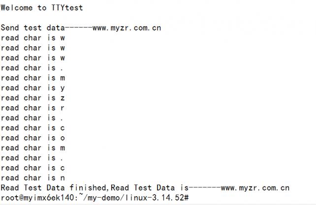
(3)./uart_test.out /dev/ttymxc2 “www.myzr.com.cn”
Test reuslt:

CAN Test
Test instruction
There are two sets of CAN interfaces on the MY-IMX6-EK140P.
| Evaluation board model | CANx | Signal Name:CAN_L | Signal Name:CAN_H | System device |
| MY-IMX6-EK140P | CAN1 | P7:1 | P7:2 | can1 |
| CAN2 | P9:1 | P9:2 | can2 |
Adopt CAN1 to send, CAN0 to receive.
Test method
(1)Connect CAN_L of CAN1 to CAN_L of CAN2; connect CAN_H of CAN1 with CAN_H of CAN2.
(2)::# ip link set can0 up type can bitrate 125000
(3)::# ip link set can1 up type can bitrate 125000
(4)::# candump can0 &
(5)::# cansend can1 1F334455::#1122334455667788
Test reuslt:

WIFI Test
Test method
(1)insmod /home/root/my-demo/linux-3.14.52/8188eu.ko
(2)wpa_passphrase WIFI name WIFI password > /etc/wpa_supplicant.conf
(3)wpa_supplicant -Dwext -iwlan0 -c/etc/wpa_supplicant.conf -B
(4)udhcpc -i wlan0
(5)Ping baidu's IP, if it can Ping, the test is successful
FXLS8471 Test
Test method
(1)# echo 1 > /sys/class/misc/FreescaleAccelerometer/enable
(2)Obtain sensor data:
- # cat /sys/class/misc/FreescaleAccelerometer/data
- # cat /sys/class/misc/FreescaleAccelerometer/data
MAG3110 Test
(1)# echo 1 > /sys/class/misc/FreescaleGyroscope/enable
(2)# evtest

Select event0 corresponding to "fxas2100x".
(3)Input 0
(4)There will be data output
SPI Test
Test instruction
(1)There are 2 SPI channels in the evaluation board,and the corresponding device file of SPI1 is /dev/spidev0.0.The file for SPI2 is /dev/spidev1.0.
(2)Taking SPI1 as an example
Test method
(1)Shorten the 3 and 4 feet of P21.
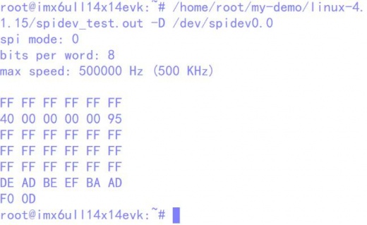
(2)Execute test command: /home/root/my-demo/linux-4.1.15/spidev_test.out -D /dev/spidev0.0
(3)Test results are shown below to indicate that the test passed

Introductions:SPI2 test method with SPI1 (the same as above).
