MYZR-RK3288-EK314 L31079 测试手册
目录
- 1 = 测试前的准备(preparation before test) =
- 2 = 测试项目(test item) =
- 3 网口测试(network inferface test)
- 4 USB测试(USB test)
- 5 SD卡测试(SD card test)
- 6 音频测试(audio test)
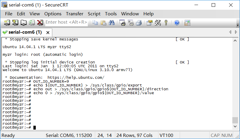
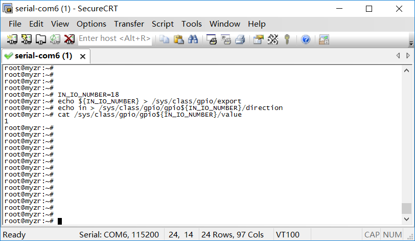
- 7 标准GPIO测试(standard GPIO test)
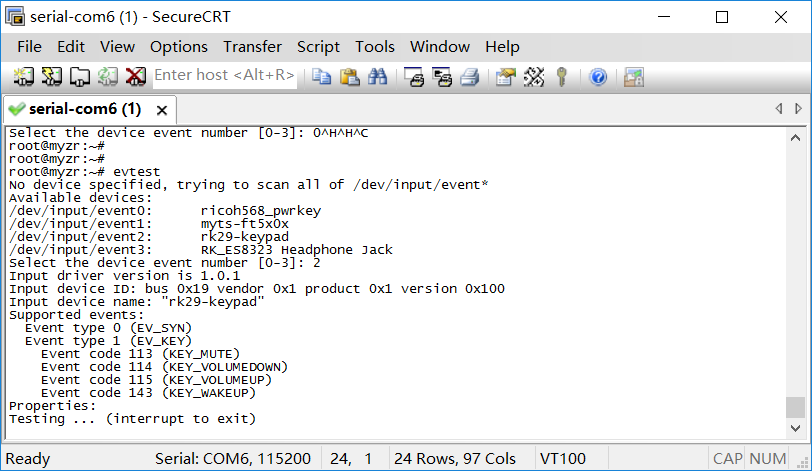
- 8 GPIO-KEY测试(GPIO-KEY test)
- 9 串口测试(serial port test)
- 10 RTC测试(RTC test)
- 11 SPI测试(SPI test)
- 12 WIFI测试(WIFI test)
- 13 蓝牙测试(Bluetooth test)
- 14 4G测试(4G internet module test)
- 15 HDMI测试(HDMI test)
- 16 EDP测试(EDP test)
= 测试前的准备(preparation before test) =
1)准备MY-RK3288-EK314开发板一套,5V直流稳压电源,USB转串口线。<br>
prepare a set of MY-RK3288-EK314 development board, 5V DC power supply, USB to serial cable.
2)接上串口线,给开发板供电,启动板子。
connect the serial cable to the development board and power/span>
= 测试项目(test item) =
网口测试(network inferface test)
MY-RK3288-EK314 评估板支持双网口,一个百兆,另一个千兆。
MY-RK3288-EK314 support two ethernet interfaces, one is 100 Mbps ethernet, the other is 1 Gbps ethernet
接口属性(interface property)
| 评估板型号 (evaluation board model no) |
接口位置 (interface position) |
接口速率标准 (interface rate standard) |
系统接口 (system interface) | ||||
|---|---|---|---|---|---|---|---|
| MY-RK3288-EK314 |
U13 |
10/100/1000Mbps
|
P1 | 10/100Mbps | eth1 |
测试方法(test method)
1) 测试说明
test instruction
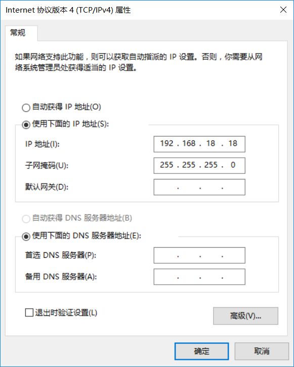
- 设置计算机有线网卡IP为192.168.18.18
set wired network card IP of computer as 192.168.18.18
2) Eth0连接测试
Eth0 connect test
- 连接网线:将评估板“eth0”对应的接口与计算机有线网卡的接口用网线相连接
connect lan line: connect “eth0”on evaluation board with corresponding wired network card interface on computer with lan line
- 设置评估板IP:
set evaluation board IP:
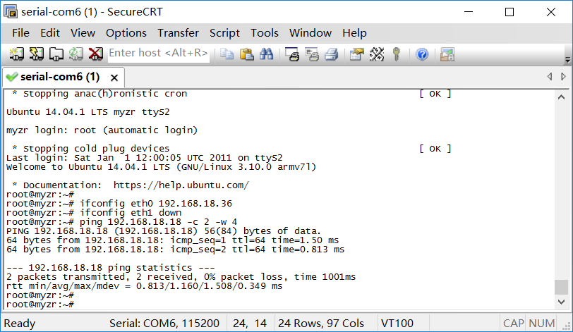
<span style="background:#ffff00># ifconfig eth0 192.168.18.36 # configure the eth0
- 执行测试命令:
execute test command:
# ifconfig eth1 down # eth1 to be shut down
# ping 192.168.18.18 -c 2 -w 4 # send ICMP to HOST
- 观察测试结果:系统会输出类似如下信息:
observe test result:system will output message like following
--- 192.168.18.18 ping statistics ---
2packets transmitted, 2 packets received, 0% packet loss
- 测试结果:“0% packet loss”表示测试通过
test result:“0% packet loss”represent test passing
- 附图
3) Eth1连接测试
Eth1 connect test
- 连接网线:将网线插入“eth1”对应的评估板接口,网线另一端保持与计算机有线网卡的接口连接。
connect lan line:insert one end of lan line into “eth1”on evaluation board and another end into wired network card interface on computer。
- 设置第2个网口IP:
set the second network inter face IP:
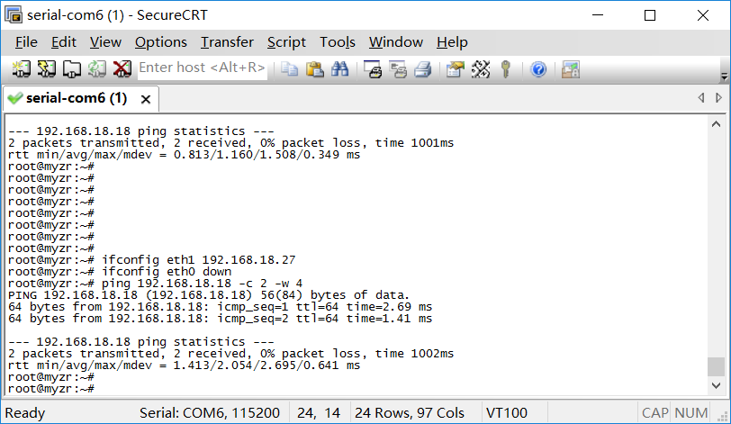
# ifconfig eth1 192.168.18.27 # configure the eth1
设置后系统会输出第2个网口的工作状态信息,类似如下:
after setting the system will output message on working condition of second network interface,like following:
smsc95xx 1-1.1:1.0 eth1: link up, 100Mbps, full-duplex, lpa 0x4DE1
- 执行测试命令:
execute test command:
# ifconfig eth0 down # eth0 to be shut down
# ping 192.168.18.18 -c 2 -w 4 # send ICMP to HOST
- 观察测试结果:系统会输出类似如下信息:
observe test result:system will output message like following:
--- 192.168.18.18 ping statistics ---
2packets transmitted, 2 packets received, 0% packet loss
- 测试结果:“0% packet loss”表示测试通过
test result:“0% packet loss”represent test passing
- 附图
USB测试(USB test)
接口属性(interface property)
| 评估板型号 (evaluation board model no.) |
接口位置 (interface position) |
接口速率标准 (interface rate standard) |
|---|---|---|
| MY-RK3288-EK314 |
J10 |
480 Mbits/s |
测试方法(test method)
1) 开始测试
start test
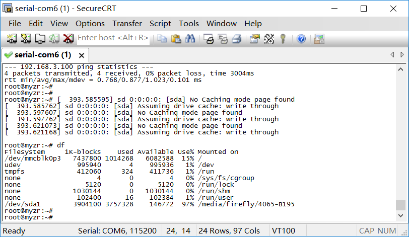
将USB设备插入底板USB接口,输入以下命令:
insert USB device into USB port on base board,enter the following command:
# df
2) 测试结束
test over
将USB设备从底板拔出,系统会输出类似如下信息:
instruction:when plug in & out U disk from USB interface,enter the following command:
# df
附图(figure)
SD卡测试(SD card test)
接口属性(interface property)
| 评估板型号 (evaluation model no.) |
接口位置 (interface position) |
接口类型 (interface type) |
|---|---|---|
| MY-RK3288-EK314 | U22 | SD |
开始测试(start test)
1) 往SD卡槽插入设备
insert device into SD card slot
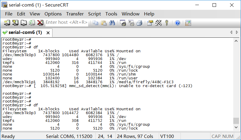
插入SD卡到底板SD卡接口,输入以下命令:
insert SD card into SD card port on base board,enter the following command:
# df
2) 结束测试
test over
SD卡弹出后拨出SD卡即结束测试。
take out SD card after SD card pop-pup,then test is over。
附图(figures)
音频测试(audio test)
测试说明(test instruction)
这项测试是通过播放音频文件验证评估板的音频功能。
the test is to verify audio function of evaluation board by playing audio file。
测试方法(test method)
1)准备测试
prepare test
连接音频输出设备到底板正面的音频座子,音频座子在底板正面“P15”。
connect audio output device to audio element in front view of base board,audio element is “J20”in front view of base board。
2)执行测试<br>
execute test
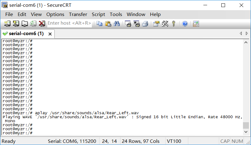
使用aplay播放一个视频,示例命令如下:
play a video with gplay,commanded as below:
# aplay /usr/share/sounds/alsa/Rear_Left.wav
上面这条命令会使用aplay播放命令中指定的文件。
the above command will play a file designated by command with gplay。
3)测试结果<br>
test result
执行上面的测试命令后会听到音频设备输出的声音。
you can see the vedeo played on display screen of evaluation board and hear the voices outputed by audio device。
