“MYZR-IMX6-EK200 启动手册”的版本间的差异
(→MY-IMX6-MB200背面图(MY-IMX6-MB200 rear view)) |
小 (Admin移动页面MY-IMX6-EK200 启动手册至MYZR-IMX6-EK200 启动手册,不留重定向) |
||
| (未显示同一用户的10个中间版本) | |||
| 第1行: | 第1行: | ||
<div> | <div> | ||
| − | = '''准备开发板套件 | + | = '''准备开发板套件''' = |
---- | ---- | ||
开发板套件由开发板和开发板配件组成。<br> | 开发板套件由开发板和开发板配件组成。<br> | ||
| − | |||
| − | == '''开发板 | + | == '''开发板''' == |
开发板由以下器件组装而成:<br> | 开发板由以下器件组装而成:<br> | ||
| − | < | + | ::*MYZR-IMX6-CB200(核心板)一片<br> |
| + | ::*MYZR-IMX6-MB200(底板)一片<br> | ||
| + | ::*显示屏电路板一片<br> | ||
| + | ::*液晶显示屏一块<br> | ||
| + | ::*触摸屏一片<br> | ||
| − | + | == '''开发板配件''' == | |
| − | |||
| − | |||
| − | |||
| − | |||
| − | |||
| − | |||
| − | |||
| − | |||
| − | |||
| − | |||
| − | == '''开发板配件 | ||
开发板配件有:<br> | 开发板配件有:<br> | ||
| − | |||
| − | |||
| − | |||
| − | |||
| − | |||
| − | |||
| − | |||
| − | |||
| − | |||
| + | ::*电源适配器1个<br> | ||
| + | ::*USB下载线1条<br> | ||
| + | ::*网线1条<br> | ||
| + | ::*串口线1条<br> | ||
| − | = '''开发板接口概览 | + | = '''开发板接口概览''' = |
---- | ---- | ||
| − | + | 在启动开发板之前我们需要认识一些接口,并将这些接口正确连接到计算机。这里我先认识MYZR-IMX6-MB314的接口。<br> | |
| − | |||
| − | == ''' | + | == '''MYZR-IMX6-MB200正面图''' == |
| − | [[文件:myimx6ek200_front.jpg| | + | [[文件:myimx6ek200_front.jpg|850px]] |
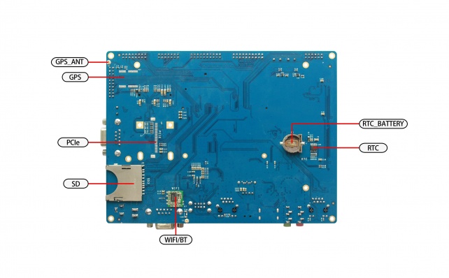
| − | == ''' | + | == '''MYZR-IMX6-MB200背面图''' == |
| − | [[文件:myimx6ek200_rear.jpg|642px]] | + | [[文件:myimx6ek200_rear view.jpg|642px]] |
| − | == '''图示模块 | + | == '''图示模块''' == |
{| class="wikitable" | {| class="wikitable" | ||
|- | |- | ||
| − | !图示<br> | + | !图示<br> |
| − | !接口描述<br> | + | !接口描述<br> |
| − | !丝印<br> | + | !丝印<br> |
|rowspan=20| | |rowspan=20| | ||
| − | !图示<br> | + | !图示<br> |
| − | !接口描述<br> | + | !接口描述<br> |
| − | !丝印<br> | + | !丝印<br> |
|- | |- | ||
|1 | |1 | ||
|18/24bit LVDS0 | |18/24bit LVDS0 | ||
| − | | | + | |J24 |
|19 | |19 | ||
| − | | | + | |RTC_Batter |
|BT1 | |BT1 | ||
|- | |- | ||
|2 | |2 | ||
|18/24bit RGB | |18/24bit RGB | ||
| − | | | + | |J23 |
|20 | |20 | ||
|UART5/TTL | |UART5/TTL | ||
| − | | | + | |J1 |
|- | |- | ||
|3 | |3 | ||
|18/24bit LVDS1 | |18/24bit LVDS1 | ||
| − | | | + | |J22 |
|21 | |21 | ||
|UART4/TTL | |UART4/TTL | ||
| − | | | + | |J1 |
|- | |- | ||
|4 | |4 | ||
| − | |10M/100M Ethernet | + | |10M/100M Ethernet-1 |
| − | | | + | |P4 |
|22 | |22 | ||
|GPIO | |GPIO | ||
| − | | | + | |J4 |
|- | |- | ||
|5 | |5 | ||
|Audio | |Audio | ||
| − | | | + | |J20 |
|23 | |23 | ||
|UART3/TTL | |UART3/TTL | ||
| − | | | + | |J1 |
|- | |- | ||
|6 | |6 | ||
|HDMI | |HDMI | ||
| − | | | + | |J5 |
|24 | |24 | ||
|UART2/TTL | |UART2/TTL | ||
| − | | | + | |J1 |
|- | |- | ||
|7 | |7 | ||
|USBOTG | |USBOTG | ||
| − | | | + | |J5 |
|25 | |25 | ||
| − | | | + | |SPI |
| − | | | + | |J7 |
|- | |- | ||
|8 | |8 | ||
|PWR_SATA | |PWR_SATA | ||
| − | | | + | |J12 |
|26 | |26 | ||
|SPI1 | |SPI1 | ||
| − | | | + | |J7 |
|- | |- | ||
|9 | |9 | ||
|SATA | |SATA | ||
| − | | | + | |J11 |
|27 | |27 | ||
|MIPI_CSI | |MIPI_CSI | ||
| − | | | + | |J9 |
|- | |- | ||
|10 | |10 | ||
|USBHOST | |USBHOST | ||
| − | | | + | |J8 |
|28 | |28 | ||
|CMOS_CSI | |CMOS_CSI | ||
| − | | | + | |J14 |
|- | |- | ||
|11 | |11 | ||
| 第142行: | 第128行: | ||
|29 | |29 | ||
|CAN2 | |CAN2 | ||
| − | | | + | |J16 |
|- | |- | ||
|12 | |12 | ||
|PWR_Switch | |PWR_Switch | ||
| − | | | + | |J3 |
|30 | |30 | ||
|CAN1 | |CAN1 | ||
| − | | | + | |J19 |
|- | |- | ||
|13 | |13 | ||
|DC_5V_IN | |DC_5V_IN | ||
| − | | | + | |J4 |
|31 | |31 | ||
|I2C3 | |I2C3 | ||
| − | | | + | |J21 |
|- | |- | ||
|14 | |14 | ||
|nRESET | |nRESET | ||
| − | | | + | |SW2 |
|32 | |32 | ||
|I2C2 | |I2C2 | ||
| − | | | + | |J21 |
|- | |- | ||
|15 | |15 | ||
| 第174行: | 第160行: | ||
|33 | |33 | ||
|I2C1 | |I2C1 | ||
| − | | | + | |J21 |
|- | |- | ||
|16 | |16 | ||
|KEY2 | |KEY2 | ||
| − | | | + | |SW4 |
|34 | |34 | ||
| 第186行: | 第172行: | ||
|17 | |17 | ||
|KEY3 | |KEY3 | ||
| − | | | + | |SW5 |
|35 | |35 | ||
|WIFI | |WIFI | ||
| − | | | + | |U16 |
|- | |- | ||
|18 | |18 | ||
|SD2 | |SD2 | ||
| − | | | + | |J4 |
|36 | |36 | ||
| − | | | + | |MINI_PCIE |
| − | | | + | |J6 |
|} | |} | ||
| − | = '''快速启动开发板 | + | = '''快速启动开发板''' = |
---- | ---- | ||
1)跳到“开发板与计算机的连接”那一节中“关闭电源开关”,“连接电源线”操作。<br> | 1)跳到“开发板与计算机的连接”那一节中“关闭电源开关”,“连接电源线”操作。<br> | ||
| − | |||
2)跳到“开发板的启动”那一节中的“为开发板上电”,从那开始继续操作。<br> | 2)跳到“开发板的启动”那一节中的“为开发板上电”,从那开始继续操作。<br> | ||
| − | |||
说明:快速启动方式下,开发板与计算机没有连接,但是从液晶屏上是可以看出系统启动状态的。<br> | 说明:快速启动方式下,开发板与计算机没有连接,但是从液晶屏上是可以看出系统启动状态的。<br> | ||
| − | |||
| − | + | = '''开发板与计算机的连接''' = | |
| − | = '''开发板与计算机的连接 | ||
---- | ---- | ||
由于在很多情况下我们需要连接开发板与计算机,下面内容将描述开发板与计算机的连接方式。<br> | 由于在很多情况下我们需要连接开发板与计算机,下面内容将描述开发板与计算机的连接方式。<br> | ||
| − | |||
| − | == '''关闭电源开关 | + | == '''关闭电源开关''' == |
| + | |||
在连接开发板与计算机之前,我们需要检查开发板电源开关状态,并确保电源开关是断开状态。<br> | 在连接开发板与计算机之前,我们需要检查开发板电源开关状态,并确保电源开关是断开状态。<br> | ||
| − | |||
使开发板电源开关处于断开的方式是:将开发板电源开关(开发板正面图的图示12)按到断开状态(—:闭合,O:断开)。<br> | 使开发板电源开关处于断开的方式是:将开发板电源开关(开发板正面图的图示12)按到断开状态(—:闭合,O:断开)。<br> | ||
| − | |||
| + | == '''串口线的连接''' == | ||
| + | === 线缆连接 === | ||
| + | 将串口线一端连接到开发板的J2(开发板正面图的图示11),一端连接到计算机。<br> | ||
| − | |||
| − | |||
| − | |||
| − | |||
如果计算机没有串口,则需要自行准备USB转串口线并连接。<br> | 如果计算机没有串口,则需要自行准备USB转串口线并连接。<br> | ||
| − | + | ||
如果没有连接串口线,将不能通过串口方式与开发板交互。但是不影响开发板的启动及烧录系统。<br> | 如果没有连接串口线,将不能通过串口方式与开发板交互。但是不影响开发板的启动及烧录系统。<br> | ||
| − | |||
| + | ===串口终端工具配置=== | ||
| + | 通过Windows的设备管理器找到计算机上我们使用端口号。<br> | ||
| − | |||
| − | |||
| − | |||
配置串口终端工具的各参数。<br> | 配置串口终端工具的各参数。<br> | ||
| − | + | ||
SecureCRT & USB串口3 示例配置如下:<br> | SecureCRT & USB串口3 示例配置如下:<br> | ||
| − | |||
[[文件:securecrt_quick_connect_com3.jpg]] | [[文件:securecrt_quick_connect_com3.jpg]] | ||
| − | + | == '''网线的连接''' == | |
| − | == '''网线的连接 | ||
将网线一端连接到开发板的P4(开发板正面图的图示4),网线另一端插入计算机的网口。<br> | 将网线一端连接到开发板的P4(开发板正面图的图示4),网线另一端插入计算机的网口。<br> | ||
| − | |||
| − | |||
| − | == '''USB下载线的连接 | + | == '''USB下载线的连接''' == |
将USB线一端连接到开发板的J8(开发板正面图的图示7),另外一端插入计算机的USB接口。<br> | 将USB线一端连接到开发板的J8(开发板正面图的图示7),另外一端插入计算机的USB接口。<br> | ||
| − | |||
| − | + | == '''连接电源线''' == | |
| − | == '''连接电源线 | ||
将电源线一端连接到开发板的J3(开发板正面图的图示13),一端连接电源插座。<br> | 将电源线一端连接到开发板的J3(开发板正面图的图示13),一端连接电源插座。<br> | ||
| − | |||
| − | |||
| − | = '''开发板的启动 | + | = '''开发板的启动''' = |
---- | ---- | ||
在“开发板与计算机的连接”中按照顺序进行操作后,我们的开发板与计算机的连接已经完成了。要使开发板启动,我们需要为开发板上电。<br> | 在“开发板与计算机的连接”中按照顺序进行操作后,我们的开发板与计算机的连接已经完成了。要使开发板启动,我们需要为开发板上电。<br> | ||
| − | |||
| − | |||
| − | == '''为开发板上电 | + | == '''为开发板上电''' == |
将开发板电源开关J3(开发板正面图的图示28)按到闭合状态(—:闭合,O:断开)。<br> | 将开发板电源开关J3(开发板正面图的图示28)按到闭合状态(—:闭合,O:断开)。<br> | ||
| − | |||
| + | == '''观察启动状况''' == | ||
| + | === 串口终端动态 === | ||
| + | 会看到计算机的串口终端有开发板启动过程中输出的启动过程信息。<br> | ||
| − | == | + | === 开发板动态 === |
| − | == | ||
| − | |||
| − | |||
| − | |||
| − | |||
启动到一定阶段后,开发板上的led灯会一直闪烁。<br> | 启动到一定阶段后,开发板上的led灯会一直闪烁。<br> | ||
| − | |||
| + | === 显示屏状态 === | ||
| + | 如果液晶显示屏正确连接,会看到在开发板的启动过程中显示屏有输出图像。<br> | ||
| − | |||
| − | |||
| − | |||
</div> | </div> | ||
| + | |||
| + | # **开发板登录** | ||
| + | |||
| + | -------------------------------------------------------------------------------- | ||
| + | 启动系统完后,可以登录: | ||
| + | 【用户名】:root | ||
| + | 【密码】:无 | ||
| + | 注:登录后可以通过“passwd”命令来设置和修改密码。 | ||
| + | <br/> | ||
2020年10月22日 (四) 11:56的最新版本
目录
准备开发板套件
开发板套件由开发板和开发板配件组成。
开发板
开发板由以下器件组装而成:
- MYZR-IMX6-CB200(核心板)一片
- MYZR-IMX6-MB200(底板)一片
- 显示屏电路板一片
- 液晶显示屏一块
- 触摸屏一片
- MYZR-IMX6-CB200(核心板)一片
开发板配件
开发板配件有:
- 电源适配器1个
- USB下载线1条
- 网线1条
- 串口线1条
- 电源适配器1个
开发板接口概览
在启动开发板之前我们需要认识一些接口,并将这些接口正确连接到计算机。这里我先认识MYZR-IMX6-MB314的接口。
MYZR-IMX6-MB200正面图

MYZR-IMX6-MB200背面图

图示模块
| 图示 |
接口描述 |
丝印 |
图示 |
接口描述 |
丝印 | |
|---|---|---|---|---|---|---|
| 1 | 18/24bit LVDS0 | J24 | 19 | RTC_Batter | BT1 | |
| 2 | 18/24bit RGB | J23 | 20 | UART5/TTL | J1 | |
| 3 | 18/24bit LVDS1 | J22 | 21 | UART4/TTL | J1 | |
| 4 | 10M/100M Ethernet-1 | P4 | 22 | GPIO | J4 | |
| 5 | Audio | J20 | 23 | UART3/TTL | J1 | |
| 6 | HDMI | J5 | 24 | UART2/TTL | J1 | |
| 7 | USBOTG | J5 | 25 | SPI | J7 | |
| 8 | PWR_SATA | J12 | 26 | SPI1 | J7 | |
| 9 | SATA | J11 | 27 | MIPI_CSI | J9 | |
| 10 | USBHOST | J8 | 28 | CMOS_CSI | J14 | |
| 11 | UART1/RS232 | P2 | 29 | CAN2 | J16 | |
| 12 | PWR_Switch | J3 | 30 | CAN1 | J19 | |
| 13 | DC_5V_IN | J4 | 31 | I2C3 | J21 | |
| 14 | nRESET | SW2 | 32 | I2C2 | J21 | |
| 15 | KEY1 | SW3 | 33 | I2C1 | J21 | |
| 16 | KEY2 | SW4 | 34 | SD3 | J18 | |
| 17 | KEY3 | SW5 | 35 | WIFI | U16 | |
| 18 | SD2 | J4 | 36 | MINI_PCIE | J6 |
快速启动开发板
1)跳到“开发板与计算机的连接”那一节中“关闭电源开关”,“连接电源线”操作。
2)跳到“开发板的启动”那一节中的“为开发板上电”,从那开始继续操作。
说明:快速启动方式下,开发板与计算机没有连接,但是从液晶屏上是可以看出系统启动状态的。
开发板与计算机的连接
由于在很多情况下我们需要连接开发板与计算机,下面内容将描述开发板与计算机的连接方式。
关闭电源开关
在连接开发板与计算机之前,我们需要检查开发板电源开关状态,并确保电源开关是断开状态。
使开发板电源开关处于断开的方式是:将开发板电源开关(开发板正面图的图示12)按到断开状态(—:闭合,O:断开)。
串口线的连接
线缆连接
将串口线一端连接到开发板的J2(开发板正面图的图示11),一端连接到计算机。
如果计算机没有串口,则需要自行准备USB转串口线并连接。
如果没有连接串口线,将不能通过串口方式与开发板交互。但是不影响开发板的启动及烧录系统。
串口终端工具配置
通过Windows的设备管理器找到计算机上我们使用端口号。
配置串口终端工具的各参数。
SecureCRT & USB串口3 示例配置如下:

网线的连接
将网线一端连接到开发板的P4(开发板正面图的图示4),网线另一端插入计算机的网口。
USB下载线的连接
将USB线一端连接到开发板的J8(开发板正面图的图示7),另外一端插入计算机的USB接口。
连接电源线
将电源线一端连接到开发板的J3(开发板正面图的图示13),一端连接电源插座。
开发板的启动
在“开发板与计算机的连接”中按照顺序进行操作后,我们的开发板与计算机的连接已经完成了。要使开发板启动,我们需要为开发板上电。
为开发板上电
将开发板电源开关J3(开发板正面图的图示28)按到闭合状态(—:闭合,O:断开)。
观察启动状况
串口终端动态
会看到计算机的串口终端有开发板启动过程中输出的启动过程信息。
开发板动态
启动到一定阶段后,开发板上的led灯会一直闪烁。
显示屏状态
如果液晶显示屏正确连接,会看到在开发板的启动过程中显示屏有输出图像。
开发板登录
启动系统完后,可以登录:
【用户名】:root
【密码】:无
注:登录后可以通过“passwd”命令来设置和修改密码。