“MYZR-IMX6-EK200 L3035测试手册”的版本间的差异
| 第1行: | 第1行: | ||
| + | <div> | ||
| + | |||
= '''测试前的准备(preparation before test)''' = | = '''测试前的准备(preparation before test)''' = | ||
---- | ---- | ||
| 第774行: | 第776行: | ||
上面两条命令即可。<br> | 上面两条命令即可。<br> | ||
<span style="background:#CCCCCC">the above two commands are applied。</span><br> | <span style="background:#CCCCCC">the above two commands are applied。</span><br> | ||
| + | </div> | ||
2018年6月11日 (一) 15:33的版本
目录
- 1 测试前的准备(preparation before test)
- 2 测试项目(test item)
- 2.1 网口测试(lan port test)
- 2.2 USB测试(USB test)
- 2.3 SD卡接口测试(SD card interface test)
- 2.4 音视频测试(A/V test)
- 2.5 LED(GPIO)测试(LED(GPIO)test)
- 2.6 按键测试(key test)
- 2.7 串口测试(serial port test)
- 2.8 RTC测试(RTC test)
- 2.9 WatchDog测试(WatchDog test)
- 2.10 SPI测试(SPI test)
- 2.11 CAN接口测试(CAN interface test)
- 2.12 PCIE接口测试(PCIE interface test)
- 2.13 WIFI测试(WIFI test)
- 2.14 IPU测试(IPU test)
- 2.15 GPU测试(GPU test)
- 2.16 VPU测试(VPU test)
- 3 显示功能测试(reveal function test)
- 4 关于环境变量的说明(instruction about environment variables)
- 4.1 MY-IMX6系列开发板环境变量的特点(features of environment variables of MY-IMX6 series of development board)
- 4.2 bootcmd_xxx 环境变量的流程(bootcmd_xxx environment variables procedure)
- 4.3 环境变量的正确设置方法(correct way to set environment variables)
- 4.4 环境变量的正确设置方法举例(example for correct way of environment variables setting)
测试前的准备(preparation before test)
1)请按照《Linux快速启动手册》中的“Linux快速启动” -> “连接设备”进行连接。
please refer to "connection of device"->"Linux fast boot" in 《Linux fast boot manual》 for the connection。
2)请按照《Linux快速启动手册》中的“Linux快速启动” -> “启动设备”进行启动。
please refer to "booting device" ->"Linux fast boot" in 《Linux fast boot manual》 for the booting。
测试项目(test item)
网口测试(lan port test)
MY-I.MX6 评估板支持双网口(2个百兆网口)。
MY-I.MX6 evalution board support dual lan port(two 100-Mbps ethernet lan ports2)。
测试说明(test instruction)
- 第1个以太网口位置底板正面“P4”,第2个以太网口位置底板正面“P5”。
the first ethernet lan port is “P4”on front view of base board,the second one is “P5”on front view of base board。
- 系统启动后默认开启第1个以太网口,并且默认IP为192.168.3.104。
defauted lan port is the first one after system boot,with defauted IP as 192.168.3.104。
测试方法(test method)
1) 测试第1个以太网口
test the first ethernet lan port
- 连接网线:用网络连接评估板“P4”与计算机网口
connect lan line:connect “P4”on evaluation board with computer lan port through network
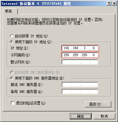
- 设置计算机IP:设置计算机网口IP为192.168.3.9
set computer IP:set computer lan port IP as 192.168.3.9
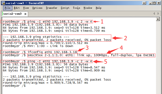
- 执行测试命令:$ ping -I eth0 192.168.3.9 -c 2 -w 4
run test command :$ ping -I eth0 192.168.3.9 -c 2 -w 4
- 观察测试结果:系统会输出类似如下信息:
observe test result:system will output following information:
--- 192.168.3.9 ping statistics ---
2packets transmitted, 2 packets received, 0% packet loss
- 测试结果:“0% packet loss”表示测试通过
test result:“0% packet loss”represent test passing
2) 测试第2个以太网口
test the second ethernet lan port
- 连接网线:拔下第1个网口的网线接口插入到评估板“P5”,网线另一端保持与计算机网口相连。
connect lan line:take out lan line from the first lan port then plug in “P5”on evaluation board,another end of lan line is kept in connection with lan port of computer。
- 设置计算机IP:设置计算机网口IP为192.168.3.9(如已经设置过可执行下一步骤)。
set computer IP:set computer lan port IP as 192.168.3.9(if the setting was already done then go direclty into next step)。
- 设置第2个网口IP:$ ifconfig eth1 192.168.3.18,设置后系统会输出第2个网口的工作状态信息,类似如下:
set the second lan port IP:$ ifconfig eth1 192.168.3.18,after the setting system will output working condition of the second lan port, as below:
smsc95xx 2-1.1:1.0: eth1: link up, 100Mbps, full-duplex, lpa 0xCDE1
- 执行测试命令:$ ping -I eth1 192.168.3.9 -c 2 -w 4
run test command:$ ping -I eth1 192.168.3.9 -c 2 -w 4
- 观察测试结果:系统会输出类似如下信息:
observe test result:system will output the following message
--- 192.168.3.9 ping statistics ---
2packets transmitted, 2 packets received, 0% packet loss
- 测试结果:“0% packet loss”表示测试通过
test result:“0% packet loss”represent test passing
附图
说明:
instruction:
第1个红框为网口1的测试命令
the first red frame is test command for lan port 1
第2个红框为网口1的测试结果
the second red frame is test result for lan port1
第3个红框为网口2的IP配置
the third red frame is IP configuration for lan port2
第4个红框为网口2的状态信息
the fourth red frame is status information for lan port2
第5个红框为网口2的测试命令
the fifth red frame is test command for lan port2
USB测试(USB test)
测试说明(test instruction)
MY-I.MX6 V2.5 评估板有2个USB HOST接口,位于底板正面“J8”。
MY-I.MX6 V2.5 evaluation board has two USB HOST ports,in“J8”in base board。
测试方法(test method)
1) 开始测试
start test
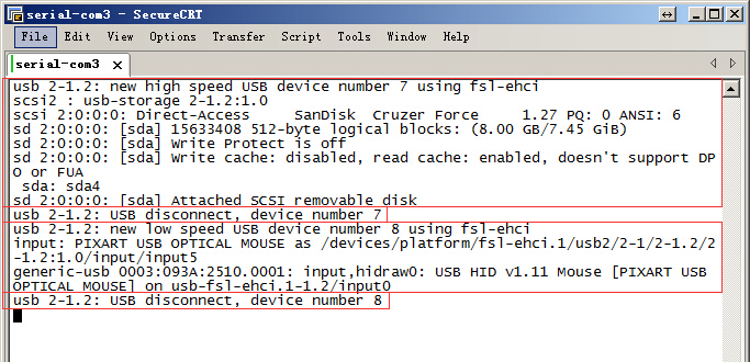
将USB设备插入底板USB接口,系统会输出类似如下信息:
plug USB device in USB port in base board,system will output the following message:
usb *-*.*: new high speed USB device number * using fsl-ehci
……
2) 测试结束
test end
将USB设备从底板拔出,系统会输出类似如下信息:
take out USB device from the base board,system will output the following message:
usb *-*.*: USB disconnect, device number *
附图(reference symbols)
说明:
instruction:
图片上第1个红框为插入U盘时系统输出的信息;
the first red frame in image is message outputed by system when insert U disk
图片上第2个红框为拔出U盘时系统输出的信息;
the second red frame in image is message outputed by system when take out U disk
图片上第3个红框为插入USB鼠标时系统输出的信息;
the third red frame in image is message outputed by system when insert USB mouse
图片上第4个红框为拔出USB鼠标时系统输出的信息。
the fourth red frame in image is message outputed by system when take out USB mouse。
SD卡接口测试(SD card interface test)
测试说明(test instruction)
SD卡接口位于底板背面“J25”。
SD card interface is in“J25”in rear view of base board。
开始测试(start test)
1) 往SD卡槽插入设备
insert device in SD card slot
插入SD卡到底板SD卡接口。系统输出以下信息(见附图)即表示SD接口正常:
insert SD card in SD card port in base board, system will output following message(see attached image),e.g.SD port is normal:
mmc*: new high speed SD card at address ****
mmcblk*: mmcx:xxxx SA**G *.**GiB
mmcblk*: p*
2)从SD卡槽弹出设备
pop-up device from SD card slot
再次住SD卡槽按下SD卡,底板会弹出SD卡。系统输出以下信息(见附图)表示SD卡接口弹出正常:
press again SD card in SD card slot,base board will pop-up SD card。system will output following message(see attached image),e.g.function of SD card port pop-up is normal:
mmc*: card **** removed
3) 结束测试
end test
SD卡弹出后拨出SD卡即结束测试。
take out SD card after SD card pop-up,to end the test。
附图(reference symbols)
音视频测试(A/V test)
测试说明(test instruction)
这项测试是通过播放有声视频验证评估板的音频功能和视频功能。
this test is to verify the function of video & audio of evaluation board by playing vocal video。
测试方法(test method)
1)准备测试
prepare test
连接音频输出设备到底板正面的音频座子,音频座子在底板正面“J20”,丝印名称是“HP”。
connect audio output device to audio element in front view of base board,audio element is “J20”in front view of base board,silkscreened as“HP”。
2)执行测试
execute test
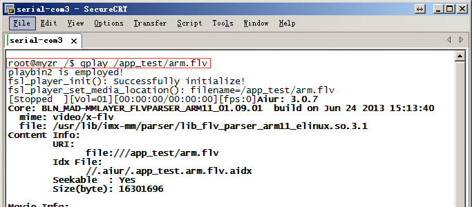
使用gplay播放一个视频,示例命令如下:
play a video with gplay,commanded as below:
$ gplay /app_test/arm.flv
上面这条命令会使用gplay播放命令中指定的文件。
the above command will play a file designated by command with gplay。
3)测试结果
test result
执行上面的测试命令后会在评估板显示屏上看到播放的视频,听到音频设备输出的声音。
you can see the vedeo played on display screen of evaluation board and hear the voices outputed by audio device。
附图(reference symbols)
LED(GPIO)测试(LED(GPIO)test)
测试说明(test instruction)
LED(GPIO)测试使用的CPU的管脚为“NANDF_CS0”,连接到底板上的“J4的4号管脚”,运行测试程序后GPIO会被测试程序控制输出高低电平。高低电平变化间隔为1秒。
CPU pin used in LED(GPIO)test is“NANDF_CS0” ,connect to “no.4 pin of J4 ”,GPIO will be controled by test programs to output high and low ectrical level after running test program,interval between high and low electrical level is 1 second。
提示:LED(GPIO)测试需要使用到万用表,没有万用表的用户可以使用跳过进行下一项测试。
CPU pin used in LED(GPIO)test is“NANDF_CS0” ,connect to “no.4 pin of J4 ”,GPIO will be controled by test programs to output high and low ectrical level after running test program,interval between high and low electrical level is 1 second。
测试方法(test method)
1)执行测试程序
execute test program
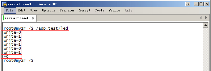
在终端下键入命令执行测试程序,示例如下:
enter command in terminal to run the test program,example as below:
$ /app_test/led
这时测试程序会控制GPIO输出高低电平,并且输出类似以下信息
at this hour GPIO will be controled by test programs to output high and low ectrical level,and output message similar to below
Write=0
Write=1
……
2)检测测试结果
check test result
把万用表的地连接到开发板的地,万用表的另一条线连接到J4的4号管脚,会看到万用表的电压跳变。
connect ground of multimeter with ground of development board,another line of multimeter is connected to no.4 pin of J4,voltage of multimeter will jump。
3)结束测试
end test
按计算机上的“Ctrl”+“C”可结束按键测试程序。
Press“Ctrl”+“C”on computer,to end the key test program。
附图(reference symbols)
按键测试(key test)
测试说明(test instruction)
MY-I.MX6底板有4个按键,其中3个为自定义功能按键(SW2:WAKE UP,SW3:V+,SW4:V-),以及1个复位按键(SW1:nRE)。测试程序key_test可以对3个功能按键进行测试。
there are 4 keys on MY-I.MX6 base board,three of them are custom function keys(SW2:WAKE UP,SW3:V+,SW4:V-),and one reset key(SW1:nRE)。test program key_test can test these 3 function keys。
测试方法(test method)
1)执行测试程序
execute test program
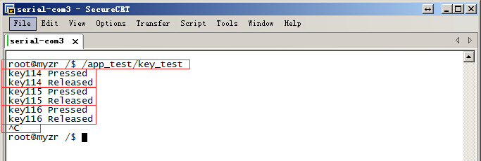
在终端下键入命令执行测试程序,示例如下:
press command in terminalto run test program,example as below:
$ /app_test/key_test
2)进行交互测试
proceed with interactive test
分别按SW4、SW3、SW2,系统会输出相应的事件信息,如:
press separately SW4、SW3、SW2,system will output corresponding message as below:
key*** Pressed
key*** Released
其中“key*** Pressed”信息是在按键被按下的时候被输出,“key*** Released”信息是在按键被松开的时候被输出。
message of“key*** Pressed”is outputed with press of key,message of“key*** Released”is outputed with release of key。
3)结束测试
end test
按计算机上的“Ctrl”+“C”可结束按键测试程序。
press “Ctrl”+“C”on computer to send the test program for keys。
注:按下SW1(系统会复位重启)。
note:press SW1(system will reset and reboot)。
附图(reference symbols)
串口测试(serial port test)
MY-I.MX6评估板有5个串口,其中4个为用户串口(位于底板正面“J1”位置,丝印名称为“TTL_UART”),1个为调试串口(位于底板正面“P2”位置)。
there are 5 serial ports in MY-I.MX6 evaluation board,4 are user serial ports(in “J1”in front view of base board,silkscreened as“TTL_UART”),one is debug serial port(in “P2”in front view of base board)。
测试说明(test instruction)
系统设备文件说明:
instruction of system device file:
- 调试串口的在系统中的设备文件是ttymxc0,用户串口的设备文件是ttymxc1、ttymxc2、ttymxc3、ttymxc4。
device file for debug serial port in the system is ttymxc0,device file for user serial port are ttymxc1、ttymxc2、ttymxc3、ttymxc4。
串口收发管脚及对应的设备文件说明:
instruction for transceiver pin of serial ports and their corresponding device file:
- UART2:发送 7,接收 9,ttymxc1。
UART2:send 7,receive 9,ttymxc1。
- UART3:发送 11,接收 13,ttymxc2。
UART3:send 11,receive 13,ttymxc2。
- UART4:发送 17,接收 15,ttymxc3。
UART4:send 17,receive 15,ttymxc3。
- UART5:发送 18,接收 16,ttymxc4。
UART5:send 18,receive 16,ttymxc4。
提示:这里列出串口的收发管脚,串口所有管脚的定义请看原理图。
tips:transceiver pins of serial port are listed here,but please refer to schematic for definition of all pins of serial port。
测试方法(test method)
采用串口自发自收的方式进行。
adopt method of self-sending & self-receiving of serial port。
提示:这里以串口5为例,其它3个用户串口参照串口的测试方法进行测试
tips:here take serial port 5 as example,please refer to serial port test method for the test of the other 3 user serial ports
1)准备测试
prepare test
短接串口5的发送发接收管脚(J1的16和18号)。
short connect sending pin and receiving pin of serial port 5(no.16 and no.18 pin of J1。
2)执行测试
execute test
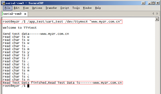
$ ~/my-demo/linux-3.0.35/uart_test.out /dev/ttymxc4 "www.myzr.com.cn"
3)测试结果
test result
如果串口正常,终端上会显示类似如下的信息:
if serial port is normal,terminal will reveal similar message as below:
Read Test Data finished,Read Test Data is-------www.myzr.com.cn
附图(reference symbols)
RTC测试(RTC test)
测试说明(test instruction)
受快递运输影响,MY-I.MX6 评估板发货时不带电池。测试RTC前请自备纽扣电池并安装到底板背面“BT1”上(在丝印“RTC”旁边)。
due to restrictions in transportation,MY-I.MX6 evaluation board doesn't contatin battery in delivery。before RTC test please prepare button cell to install on “BT1”in rear view of base board(beside silkscreened name of“RTC”)。
测试方法(test method)
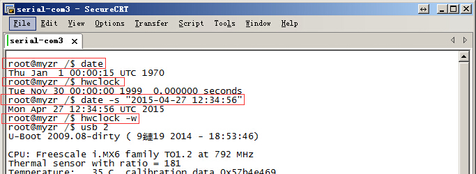
1)断电重启设备,查看当前系统时间和硬件时间。
power off then reboot device,to check the time of system and hardware。
查看当前系统时钟命令如下:
command to check clock of current system as below:
$ date
系统输出信息如下:
message outputed by system as below:
Thu Jan 1 00:00:59 UTC 1970
查看当前RTC芯片时钟命令如下:
command to check clock of RTC chip as below:
$ hwclock
系统输出信息如下:
message outputed by system as below:
Tue Nov 30 00:00:00 1999 0.000000 seconds
2)设置系统时钟,并同步到RTC芯片
set system clock and synchronously set to RTC chip
设置系统时钟命令参考如下:
command to set system clock are with below reference:
$ date -s "2015-04-27 12:34:56"
将系统时钟写入硬件时钟命令如下:
command to write system clock into hardware as below:
$ hwclock –w
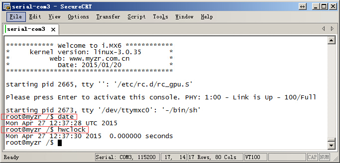
3)断电重启评估板,查看当前系统时钟和硬件时钟
power off and reboot evaluation board,to check current system clock and hardware clock
请参考第1步
please refer to step 1
4)测试结果
test result
执行第3步以后看到的时钟为新设定的时钟。
it will be a newly-set clock after execution until step 3。
附图(reference symbols)
下图为测试方法中步骤1和2的截图
below image is screenshots for step1 and step 2 in the test
下图为测试方法中步骤3的截图
below image is the screenshots for step3 in the test
WatchDog测试(WatchDog test)
测试说明(test instruction)
WatchDog测试包括2项:一项是复位测试,一项是喂狗测试。
WatchDog test includes two items:one is reset test,the other is feed dog test。
复位测试(reset test)
1)测试说明
test instruction
复位测试将启动WatchDog,但是并不喂狗,60秒后系统将会复位。
reset test will boot WatchDog,but doesn't feed dog,system will reset after 60 seconds。
2)执行测试
execution test
运行/app_test/watdogrestart,示例命令如下:
run/app_test/watdogrestart,instanced command as below:
$ /app_test/watdogrestart
3)测试结果
test result
运行测试命令后等待60秒后,WatchDog超时,系统被复位。将会在终端看到系统重新启动输出的信息。
wait for 60 seconds after running of test command,WatchDog timeout,system is resetted。you can see message outputed by system rebooting on terminal。
喂狗测试(dog feeding test)
1)测试说明
test instruction
喂狗测试将启动WatchDog,并且每1秒钟进行1次喂狗,系统将不会因为WatchDog超时而复位。
feeding dog test will boot WatchDog,and feed dog once a second,system won't reset because of WatchDog timeout。
2)执行测试
execute test
运行/app_test/watdogtest &,示例命令如下:
run/app_test/watdogtest &,instanced example as below:
$ /app_test/watdogtest &
3)测试结果
test result
运行测试命令后,系统依然正常工作,并不会因为WatchDog超时而复位。
after run the test command,system still works normally and won't reset because of WatchDog timeout。
SPI测试(SPI test)
MY-I.MX6 V2.5底板上有一组SPI接口,在“J7”位置,丝印为“SPI”。
there are a group of SPI ports on MY-I.MX6 V2.5 base board,located on“J7”,silkscreened as “SPI”。
测试说明(test instruction)
测试需要用到SPI接口的MISO和MOSI管脚。SPI接口的 MISO管脚在底板“J7的8号”,MOSI管脚为“J7的10号”。
MISO pin and MOSI pin of SPI port will be used for the test。SMISO pin of SPI port is “no.8 of J7”on the base board,and MOSI pin is “no.10 of J7”。
测试方法(test method)
采用SPI自发送(输出)自接收(输入)的方式。
adopt way of SPI self-sending(output)self-receiving(input。)
1)准备测试
prepare test
短接SPI的MISO和MISO管脚,即短接底板上J7的8号和10号管脚。
short connect MISO pin and MISO pin of SPI port,e.g.short connect pin no.8 and pin no.10 of J7 on the base board。
2)执行测试
execute test
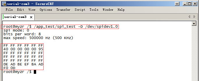
$ ~/my-demo/linux-3.0.35/spidev_test.out -D /dev/spidev1.0
3)测试结果
test result
如果SPI正常,在终端上会看到如下字符:
if SPI is normal,you can see on terminal the following charaters:
FF FF FF FF FF FF
40 00 00 00 00 95
FF FF FF FF FF FF
FF FF FF FF FF FF
FF FF FF FF FF FF
DE AD BE EF BA AD
F0 0D
附图(figured)
CAN接口测试(CAN interface test)
测试说明(test instruction)
CAN测试需要用到示波器,没有示波器的客户请跳过CAN测试。
oscilloscope will be used for CAN test,please skip this step for users who don't have oscilloscope。
测试方法(test method)
1)配置CAN0
configuration CAN0
示例命令如下:
instanced example as below:
$ ip link set can0 up type can bitrate 250000
2)配置连接示波器
configuration of link for oscilloscope
将示波器的CH1和CH2连接到评估板的“R83”(在底板正面最上面的绿色座子)。
connect CH1 and CH2 with “R83”of evaluation board(the green stand on topside on front view of base board)。
配置示波器(不会使用示波器的客户请找硬件工程师协助)。
configure oscilloscope(for users who don't know how to use oscilloscope ,please ask hardware engineers for assistance )。
3)执行测试命令
execute test command
$ /app_test/client_test
4)测试结果
rest result
执行测试命令的同时会在示波器上看到波形的变化。
when exectue the test command,you can see a waving change on oscilloscope。
附图(figured)
PCIE接口测试(PCIE interface test)
测试说明(test instruction)
系统已添加PCI接口的驱动,在启动过程中系统会检测PCI-E接口上的设备。
system is already added with drivers for PCI port,in booting system will check out devices on PCI-E interface。
测试方法(test method)
复位系统,观察系统启动输出的信息
reset system,observe the message outputed by system booting
1)PCI-E驱动程序输出信息
PCI-E driving program output messages
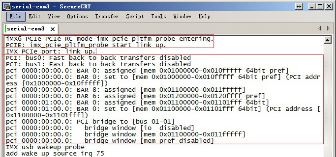
在系统启动过程中输出如下信息表示PCI-E接口驱动加载没有问题:
in the course of system booting, if there is outputed message as below,e.g PCI-E interface load is normal:
iMX6 PCIe PCIe RC mode imx_pcie_pltfm_probe entering.
PCIE: imx_pcie_pltfm_probe start link up.
2)不连接PCI-E设备时的输出信息
message outputed without link of PCI-E device
在系统启动过程中,如果PCI-E接口上没有连接有效的设备,系统会提示PCI-E端口“link down!”,类似如下:
in the course of system booting,it there is not a valid device linked with PCI-E interface,system will prompt“link down!”on PCI-E port,something as below:
link up failed, DB_R0:0x00361900, DB_R1:0x08200000!
IMX PCIe port: link down!
3)连接有效PCI-E设备时的输出信息(这里以Intel 4965AGN为例)
message outputed when there is a valid PCI-E device linked(here take Intel 4965AGN as an example)
在系统启动过程中,如果PCI-E接口上检测到有效的设备,并且设备模块正常,系统会提示PCI-E端口“link up”,如下:
in the course of system booting,if PCI-E port detect a valid device and the device module is normal,system will prompt“link up”on PCI-E port,as below:
IMX PCIe port: link up.
4)Linux测试命令:$ lspci
Linux test command:$ lspci
如果在PCI-E接口上插入了有效的PCI-E设备,使用lspci将会得到该模块相关的信息,类似如下(这里连接的是Intel 4965AGN):
if a valid PCI-E device is inserted on PCI-E port,information related to the module will be gained with lspci,something like this(what is linked is Intel 4965AGN in this case):
00:00.0 Class 0604: 16c3:abcd
01:00.0 Class 0280: 8086:4229
如果PCI-E接口上没有连接设备,使用lspci系统将没有信息输出。
if there is not device linked with PCI-E port,lspci system won't output any message。
附图(figured)
下图为未连接PCI-E设备时系统输出的信息
following figure is message outputed by system without a link with PCI-E device

下图为连接Intel 4965AGN时系统输出的信息
the following figure is message ouputed by system with a link to Intel 4965AGN
下图为连接Intel 4965AGN后,进入系统使用lspci得到的信息
following figure is message by use of lspci after entering system on the condition of a link with Intel 4965AGN

WIFI测试(WIFI test)
测试说明(test instruction)
MY-I.MX6 评估板使用的WIFI芯片型号为RTL8188EUS。
model no. of WIFI chip ussed for MY-I.MX6 evaluation board is RTL8188EUS。
测试方法(test method)
1)加载WIFI模块驱动
load WIFI module driver
示例命令如下:
instanced command as below:
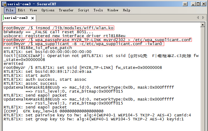
$ insmod /lib/modules/wifi/wlan.ko
2)生成WIFI的config文件
generate WIFI config file
参考命令如下:
refered command as below:
$ wpa_passphrase MYZR_TP-LINK myzrd2302 > /etc/wpa_supplicant.conf
这条命令指定的WIFI名称是和密码是“MYZR_TP-LINK myzrd2302”,需要替换成自己可连接的WIFI名称和密码。
both name and password of WIFI designated by this command are “MYZR_TP-LINK myzrd2302”,need to replace with your own linkable WIFI name and password。
3)连接WIFI网络
link WIFI network
示例命令如下:
instanced command as below:
$ wpa_supplicant -B –c /etc/wpa_supplicant.conf -iwlan0
4)自动获取IP
automaically gain IP
示例命令如下:
instanced command as below:
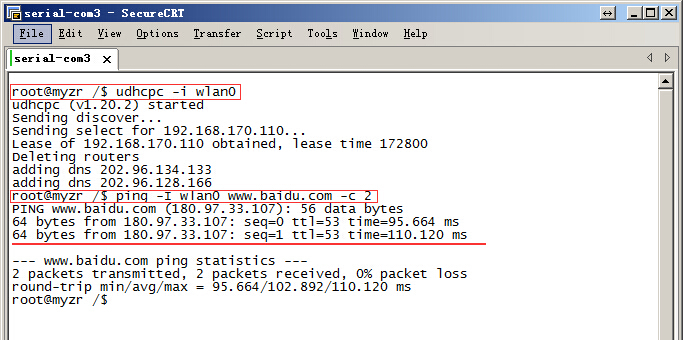
$ udhcpc -i wlan0
注意:这里需要确认所在的WIFI网络已启用DHCP功能。
note:need to ensure a DHCP function opened for WIFI network in use。
5)测试WIFI网络连接
test WIFI network link
示例命令如下:
instanced command as below:
$ ping -I wlan0 www.baidu.com -c 2
6)测试结果
test result
执行步骤5能ping通则表示WIFI模块工作正常。
execute step 5 if ok, e.g. WIFI module is normal to work。
附图(figured)
IPU测试(IPU test)
测试说明(test instruction)
整个IPU测试过程完成需要十几分钟。
the whole IPU test will take over ten minutes 。
测试方法(test method)
1)执行测试
execute test
进入测试程序所在目录(一定要进入测试程序所在目录才能正常执行测试脚本)
enter directory where test program is located(must enter directory where test program is locased for a normal test script)
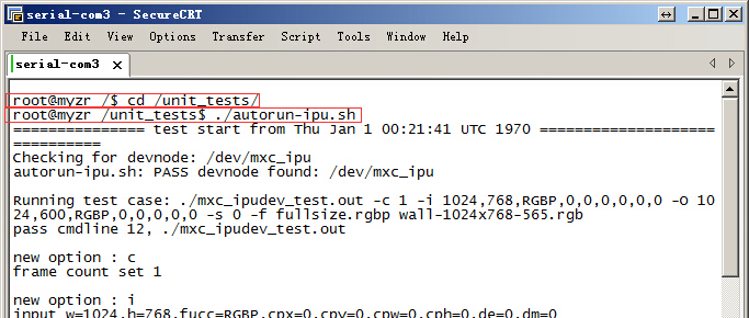
$ cd /unit_tests/
执行测试脚本
execute test script
$ ./autorun-ipu.sh
2)测试结果
test result
在整个测试过程中,可以看到显示屏显示的内容在不停的变化。
in the whole test process,you can see a constant change of content on the display screen。
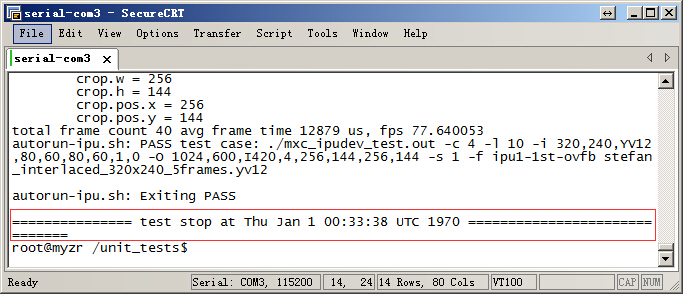
测试完成后,在终端上可以看到类似如下信息:
after test is over,you can see on terminal the following message:
test stop at Thu Jan 1 00:33:38 UTC 1970
附图(figured)
GPU测试(GPU test)
测试说明(test instruction)
测试具体内容请跟踪 /unit_tests/gpu.sh 文件。
please follow /unit_tests/gpu.sh file for the details of test。
测试方法(test method)
1)执行测试
execute test
进入测试程序所在目录(一定要进入测试程序所在目录才能正常执行测试脚本)
enter directory where test program is located(must enter directory where test program is locased for a normal test script)
$ cd /unit_tests/
* 执行测试脚本
execute test script
$ ./gpu.sh
2)测试过程
test process
在整个测试过程中,可以看到显示屏显示的内容在不停的变化。
in the whole test process,you can see a constant change of content on the display screen。
3)退出测试
exit test
终端输出“press ESC to escape...”,按ESC可退出测试。
terminal output“press ESC to escape...”,press ESC to exit test。
附图(figured)
VPU测试(VPU test)
测试说明(test instruction)
测试过程将使用VPU解码视频文件并输出到显示设备。
in the test,vedio file will be decoded with VPU and outputed to the display device。
测试方法(test method)
1)执行测试
execute test
进入测试程序所在目录(一定要进入测试程序所在目录才能正常执行测试脚本)
enter directory where test program is located(must enter directory where test program is locased for a normal test script)
$ cd /unit_tests/
* 执行测试脚本
execute test script
$ ./autorun-vpu.sh
2)测试过程
test process
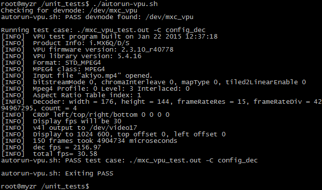
在整个测试过程中,从显示屏上可以看到VPU解码的视频。
in the whole test process,you can see the vedio decoded by VPU on the display screen。
附图(figured)
显示功能测试(reveal function test)
说明:每项显示功能测试都需要重启系统进入到u-boot命令行,输入命令并按确认键。
instruction:need to re-boot system to enter u-boot command line for each reveal function test,enter command and press Enter key。
示例如下:
example as below:
单屏显示(single screen display)
说明:输入命令并按确定键,观察系统启动过程中显示屏的显示内容,即可看到Linux Logo。
instruction:enter command and press Enter key,observe the displayed content on screen in the course of system booting,Linux Logo can be seen。
LVDS1
将显示屏排线插入LVDS1(位于底板正面“J22”位置,丝印名称为“LVDS1”),启动系统,进入u-boot命令行,输入下面命令并按确定键:
insert ribbon cable for screen to LVDS1(in “J22”on front view of base board,silkscreened as“LVDS1”),boot system,enter u-boot command line,enter the following commands and press Enter key:
setenv bootargs console=ttymxc0,115200 ip=none root=/dev/mmcblk0p1 rootwait video=mxcfb0:dev=ldb,LDB-1024X600,if=RGB666; mmc dev 2; mmc read 0x10800000 0x800 0x2000; bootm
LVDS0
将显示屏排线插入LVDS0(位于底板正面“J24”位置,丝印名称为“LVDS0”),运行系统进入u-boot命令行,输入下面命令并按确定键:
insert ribbon cable for screen to LVDS0(in“J24”on front view of base board,silkscreened as“LVDS0”),run system to enter u-boot command line,enter the following commands and press Enter key:
setenv bootargs console=ttymxc0,115200 ip=none root=/dev/mmcblk0p1 rootwait video=mxcfb0:dev=ldb,LDB-1024X600,if=RGB666 ldb=sin0; mmc dev 2; mmc read 0x10800000 0x800 0x2000; bootm
HDMI
setenv bootargs console=ttymxc0,115200 ip=none root=/dev/mmcblk0p1 rootwait video=mxcfb0:dev=hdmi,1920x1080M@60,if=RGB24; mmc dev 2; mmc read 0x10800000 0x800 0x2000; bootm
提示:HDMI显示在启动过程中屏幕无Linux Logo显示。进入系统后可以使用gplay命令播放视频,可以看到视频转出在显示屏上。
tips:there is not reveal of Linux Logo on screen for HDMI display in booting。vedio can be played with gplay command after entering system,vedio transfered can be seen on display screen。
视频播放命令示例如下:
example for vedio playing command as below:
$ gplay /unit_tests/akiyo.mp4
RGB
进入u-boot命令行,输入下面命令并按确定键:
enter u-boot command line,enter the following commands and press Enter key:
setenv bootargs console=ttymxc0,115200 ip=none root=/dev/mmcblk0p1 rootwait video=mxcfb0:dev=lcd,SEIKO-WVGA,if=RGB24; mmc dev 2; mmc read 0x10800000 0x800 0x2000; bootm
双屏同步骤显示(dual screens synchronous display)
说明:输入命令并按确定键,在内核启动过程中可以看到两个屏幕都显示Linux Logo,并且其它对显示屏的操作也会同样显示在两个屏幕上。
instruction:enter command and press Enter key,Linux Logo is displayed on the two screens in kernel booting,and other operations to screen is also displayed on the two screens。
LVDS1+LVDS0同步显示(LVDS1+LVDS0 synchronous display)
setenv bootargs console=ttymxc0,115200 ip=none root=/dev/mmcblk0p1 rootwait video=mxcfb0:dev=ldb,LDB-1024X600,if=RGB666 ldb=dul0 video=mxcfb1:dev=ldb,LDB-1024X600,if=RGB666; mmc dev 2; mmc read 0x10800000 0x800 0x2000; bootm
双屏异步显示(dual screen asynchronous display)
会用到的测试命令(test commands probably to be used)
- 打开主显示屏的背光
turn on backlight of main display screen
$ echo 0 > /sys/class/graphics/fb0/blank
- 打开第2显示屏的背光
turn on backlight of the second display screen
$ echo 0 > /sys/class/graphics/fb2/blank
- 播放指定的视频文件到视频设备(这里video17关联到主显示屏)
play the designated vedio file to vedio device(here video17 is related to main screen)
$ gst-launch playbin2 uri=file:///unit_tests/akiyo.mp4 \
video-sink="mfw_v4lsink device=/dev/video17"
- 播放指定的视频文件到视频设备(这里video18关联到第2显示屏)
play the designated vedio file to vedio device(here video18 is related to the second screen)
$ gst-launch playbin2 uri=file:///unit_tests/akiyo.mp4 \
video-sink="mfw_v4lsink device=/dev/video18"
测试方法说明(instruction of test method)
1)进入u-boot命令行输入命令并按确认键待系统启动完成。
enter u-boot command line and enter commands then press Enter key and wait until booting is over。
示例如下:
example as below:
2)执行命令打开对应显示屏的背光。
execute command turn on backlight of corresponding display screen。
示例如下:
example as below:
3)执行视频播放命令播放视频到显示屏。
execute vedio playing command to play the vedio to display screen。
示例如下:
example as below:
说明:双屏异步显示模式下,系统启动后第2显示屏的背光默认是关闭的,所以需要执行步骤2)。
instruction:in the mode of dual screen asynchronous display ,the backlight defaut of the second screen is closed after system boot,so need to execute step2)。
LVDS1作为主屏(LVDS1 as main screen)
- LVDS1+LVDS0双屏异步显示
LVDS1+LVDS0 dual screen asynchronous display
setenv bootargs console=ttymxc0,115200 ip=none root=/dev/mmcblk0p1 rootwait video=mxcfb0:dev=ldb,LDB-1024X600,if=RGB666 video=mxcfb1:dev=ldb,LDB-1024X600,if=RGB666; mmc dev 2; mmc read 0x10800000 0x800 0x2000; bootm
- LVDS1+RGB双屏异步显示
LVDS1+RGB dual screen asynchronous display
setenv bootargs console=ttymxc0,115200 ip=none root=/dev/mmcblk0p1 rootwait video=mxcfb0:dev=ldb,LDB-1024X600,if=RGB666 video=mxcfb1:dev=lcd, SEIKO-WVGA,if=RGB24; mmc dev 2; mmc read 0x10800000 0x800 0x2000; bootm
- LVDS1+HDMI双屏异步显示
LVDS1+HDMI dual screen asynchronous display
setenv bootargs console=ttymxc0,115200 ip=none root=/dev/mmcblk0p1 rootwait video=mxcfb0:dev=ldb,LDB-1024X600,if=RGB666 video=mxcfb1:dev=hdmi,1920x1080M@60,if=RGB24; mmc dev 2; mmc read 0x10800000 0x800 0x2000; bootm
LVDS0作为主屏(LVDS0 as main screen)
- LVDS0+LVDS1双屏异步显示:
LVDS0+LVDS1 dual screen asynchronous display:
setenv bootargs console=ttymxc0,115200 ip=none root=/dev/mmcblk0p1 rootwait video=mxcfb0:dev=ldb,LDB-1024X600,if=RGB666 ldb=sep0 video=mxcfb1:dev=ldb,LDB-1024X600,if=RGB666; mmc dev 2; mmc read 0x10800000 0x800 0x2000; bootm
- LVDS0+RGB双屏异步显示
LVDS0+RGB dual screen asynchronous display
setenv bootargs console=ttymxc0,115200 ip=none root=/dev/mmcblk0p1 rootwait video=mxcfb0:dev=ldb,LDB-1024X600,if=RGB666 ldb=sin0 video=mxcfb1:dev=lcd,SEIKO-WVGA,if=RGB24; mmc dev 2; mmc read 0x10800000 0x800 0x2000; bootm
- LVDS0+HDMI双屏异步显示
LVDS0+HDMI dual screen asynchronous display
setenv bootargs console=ttymxc0,115200 ip=none root=/dev/mmcblk0p1 rootwait video=mxcfb0:dev=ldb,LDB-1024X600,if=RGB666 ldb=sin0 video=mxcfb1:dev=hdmi,1920x1080M@60,if=RGB24; mmc dev 2; mmc read 0x10800000 0x800 0x2000; bootm
RGB作为主屏(RGB as main screen)
- RGB+LVDS1双屏异步显示:
RGB+LVDS1 dual screen asynchronous display:
setenv bootargs console=ttymxc0,115200 ip=none root=/dev/mmcblk0p1 rootwait video=mxcfb0:dev=lcd,SEIKO-WVGA,if=RGB24 video=mxcfb1:dev=ldb,LDB-1024X600,if=RGB666; mmc dev 2; mmc read 0x10800000 0x800 0x2000; bootm
- RGB+LVDS0双屏异步显示:
RGB+LVDS0 dual screen asynchronous display:
setenv bootargs console=ttymxc0,115200 ip=none root=/dev/mmcblk0p1 rootwait video=mxcfb0:dev=lcd,SEIKO-WVGA,if=RGB24 video=mxcfb1:dev=ldb,LDB-1024X600,if=RGB666 ldb=sin0; mmc dev 2; mmc read 0x10800000 0x800 0x2000; bootm
HDMI作为主屏(HDMI as main screen)
- HDMI+LVDS1双屏异步显示
HDMI+LVDS1 dual screen asynchronous display
setenv bootargs console=ttymxc0,115200 ip=none root=/dev/mmcblk0p1 rootwait video=mxcfb0:dev=hdmi,1920x1080M@60,if=RGB24 video=mxcfb1:dev=ldb,LDB-1024X600,if=RGB666; mmc dev 2; mmc read 0x10800000 0x800 0x2000; bootm
- HDMI+LVDS0双屏异步显示
HDMI+LVDS0 dual screen asynchronous display
setenv bootargs console=ttymxc0,115200 ip=none root=/dev/mmcblk0p1 rootwait video=mxcfb0:dev=hdmi,1920x1080M@60,if=RGB24 video=mxcfb1:dev=ldb,LDB-1024X600,if=RGB666 ldb=sin0; mmc dev 2; mmc read 0x10800000 0x800 0x2000; bootm
关于环境变量的说明(instruction about environment variables)
MY-IMX6系列开发板环境变量的特点(features of environment variables of MY-IMX6 series of development board)
MY-IMX6 系列开发板的环境变量具有以下特点:
environment variables of MY-IMX6 series of development board feature as below:
1. 从引导内核的介质来区说,有:eMMC、网络(tftp)。
medium leading kernel includes:eMMC、network(tftp)。
2. 从引导文件系统的介质来说,有:eMMC、网络(NFS)。
medium leading file system includes:eMMC、network(NFS)。
3. 从显示设备的配置来说,有 LVDS0、LVDS1、HDMI、RGB,以及双屏不同的组合。
configuration for display device includes: LVDS0、LVDS1、HDMI、RGB,and different combinations of dual screens。
这时候,如果环境变量把上面三种都组合,会有不少于60条的 bootcmd 环境变量,所以我们对环境变量进行了抽象分离及重组。
in this case,if environment variables combine the three features mentioned above ,there will be at least 60 bootcmd environment variables,so we conduct abstract separation and recombination for environment variables.
再由于 bootargs 环境变量里包括 console、video、ip、root 等其它参数,所以每一种 bootcmd 对 bootargs 有很强的依赖性,以及不同的 bootcmd 之间的差别较大。无疑,bootargs 是不能通用的。
since bootargs environment variables include parameter such as console、video、ip、root ,so each kind of bootcmd rely a lot on bootargs ,plus a big difference among different kinds of bootcmd,it is no question that bootargs are not universial。
bootcmd_xxx 环境变量的流程(bootcmd_xxx environment variables procedure)
我们对 bootcmd 及 bootargs 按引导设备进行了抽象,抽象后 bootcmd_xxx 的流程是这样的:
we abstract bootcmd and bootargs based on guided device,after abstraction bootcmd_xxx procedure like this:
1. 通过 bootargs_base 重设 bootargs,这样确保 bootargs 中不存在冲突;
re-build bootargs through bootargs_base,to ensure no conflict among bootargs;
2. 通过 bootargs_xxx 在 bootargs 后面添加与引导设备对应的参数;
parameters corresponding to guided device are added after bootargs through bootargs_xxx;
再就 bootcmd_xxx 中“;”之后的内容就是大家很容易理解的了。
as to “;”in bootcmd_xxx ,the following will be easily understood.
环境变量的正确设置方法(correct way to set environment variables)
关于对环境变量正确设置的方法:
as to the correct ways to set environment variables:
首先需要注意的是,正常情况下直接对 bootargs 设置是会无效的,因为 bootargs_base 会重设 bootargs。
must be noted that setting to bootargs in normal condition is invalid,because bootargs_base will re-set bootargs。
需要把 bootargs 的设置写到 bootargs_base 的命令当中。
need to write the setting of bootargs to the commands of bootargs_base 。
bootargs_base 所包含的内容应当只是 console 和 video,再其它的参数应当写到 bootargs_mmc 或 bootcmd_tftp 或 bootargs_nfs 中。
bootargs_base contains only console and video,other parameters should be written to bootargs_mmc or bootcmd_tftp or bootargs_nfs 。
环境变量的正确设置方法举例(example for correct way of environment variables setting)
如需要设置“HDMI+LVDS1双屏异步显示”并保存环境变量,则:
if need to set “HDMI+LVDS1 dual screen asynchronous display”and reserve environment variables,then:
1. setenv bootargs_base 'setenv bootargs console=ttymxc0,115200 video=mxcfb0:dev=hdmi,1920x1080M@60,if=RGB24 video=mxcfb1:dev=ldb,LDB-1024X600,if=RGB666'
2. saveenv
上面两条命令即可。
the above two commands are applied。

