“MYZR-IMX6-EK336启动手册”的版本间的差异
来自明远智睿的wiki
(→正面图(MB314 + CB336)(front view(MB314+CB336)) |
|||
| 第1行: | 第1行: | ||
<div> | <div> | ||
| − | = '''准备开发板套件 | + | = '''准备开发板套件''' = |
---- | ---- | ||
| − | 开发板套件由开发板和开发板配件组成。 | + | 开发板套件由开发板和开发板配件组成。<br> |
| − | + | ||
| − | == '''开发板 | + | == '''开发板''' == |
开发板由以下器件组装而成:<br> | 开发板由以下器件组装而成:<br> | ||
| − | + | ::*核心板: MY-IMX6-CB336 一片<br> | |
| − | * 核心板: MY-IMX6-CB336 一片<br> | + | ::*底板: MY-IMX6-MB314 一片<br> |
| − | + | ::*显示屏电路板一片<br> | |
| − | * 底板: MY-IMX6-MB314 一片<br> | + | ::*液晶显示屏一块<br> |
| − | + | ::*触摸屏一片<br> | |
| − | * 显示屏电路板一片<br> | ||
| − | |||
| − | * 液晶显示屏一块<br> | ||
| − | |||
| − | * 触摸屏一片 | ||
| − | |||
| − | == '''开发板配件 | + | == '''开发板配件''' == |
开发板配件有:<br> | 开发板配件有:<br> | ||
| − | + | ::*电源适配器1个<br> | |
| − | * 电源适配器1个<br> | + | ::*USB下载线1条<br> |
| − | + | ::*网线1条<br> | |
| − | * USB下载线1条<br> | + | ::*串口线1条<br> |
| − | + | ||
| − | * 网线1条<br> | + | = '''开发板接口概览''' = |
| − | |||
| − | * 串口线1条<br> | ||
| − | |||
| − | = '''开发板接口概览 | ||
---- | ---- | ||
| − | 在启动开发板之前我们需要认识一些接口,并将这些接口正确连接到计算机。这里我先认识MY-IMX6-MB314的接口。 | + | :在启动开发板之前我们需要认识一些接口,并将这些接口正确连接到计算机。这里我先认识MY-IMX6-MB314的接口。<br> |
| − | + | == '''MY-IMX6-(MB314 + CB336)正面图''' == | |
| − | == '''MY-IMX6-(MB314 + CB336) | + | [[文件:MY-IMX6-EK336-front.jpg|642px]]<br> |
| − | [[文件:MY-IMX6-EK336-front.jpg|642px]] | + | == '''MY-IMX6-MB314 + CB336背面图''' == |
| − | + | [[文件:MY-IMX6-EK336-back.jpg|642px]]<br> | |
| − | == '''MY-IMX6-MB314 + | ||
| − | [[文件:MY-IMX6-EK336-back.jpg|642px]] | ||
| − | = '''快速启动开发板 | + | = '''快速启动开发板''' = |
---- | ---- | ||
1)跳到“开发板与计算机的连接”那一节中“关闭电源开关”,“连接电源线”操作。<br> | 1)跳到“开发板与计算机的连接”那一节中“关闭电源开关”,“连接电源线”操作。<br> | ||
| − | |||
| − | |||
2)跳到“开发板的启动”那一节中的“为开发板上电”,从那开始继续操作。<br> | 2)跳到“开发板的启动”那一节中的“为开发板上电”,从那开始继续操作。<br> | ||
| − | + | :注意:快速启动方式下,开发板与计算机没有连接,但是在液晶屏上是可以看到系统启动过程的。<br> | |
| − | + | = '''开发板与计算机的连接''' = | |
| − | |||
| − | = '''开发板与计算机的连接 | ||
---- | ---- | ||
由于在很多情况下我们需要连接开发板与计算机,下面内容将描述开发板与计算机的连接方式。<br> | 由于在很多情况下我们需要连接开发板与计算机,下面内容将描述开发板与计算机的连接方式。<br> | ||
| − | |||
| − | == '''关闭电源开关 | + | == '''关闭电源开关''' == |
| − | 在连接开发板与计算机之前,我们需要检查开发板电源开关状态,并确保电源开关是断开状态。<br> | + | *在连接开发板与计算机之前,我们需要检查开发板电源开关状态,并确保电源开关是断开状态。<br> |
| − | + | *使开发板电源开关处于断开的方式是:将开发板电源开关(开发板正面图的图示”PWR_SWITCH”)按到断开状态(—:闭合,O:断开)。<br> | |
| − | |||
| − | 使开发板电源开关处于断开的方式是:将开发板电源开关(开发板正面图的图示”PWR_SWITCH”)按到断开状态(—:闭合,O:断开)。 | ||
| − | |||
== '''串口线的连接(connection of serial line)''' == | == '''串口线的连接(connection of serial line)''' == | ||
=== 线缆连接(cable connection) === | === 线缆连接(cable connection) === | ||
| − | + | *将串口线一端连接到开发板的调试串口(开发板正面图的图示“RS232_UART1”),一端连接到计算机。<br> | |
| − | < | + | *如果计算机没有串口,则需要自行准备USB转串口线并连接。<br> |
| + | *如果没有连接串口线,将不能通过串口方式与开发板交互。但是不影响开发板的启动及烧录系统。<br> | ||
| − | + | ===''' 串口终端工具配置'''=== | |
| − | < | + | *通过Windows的设备管理器找到计算机上我们使用端口号。<br> |
| + | *配置串口终端工具的各参数。<br> | ||
| + | :::SecureCRT & USB串口3 示例配置如下:<br> | ||
| + | :::[[文件:securecrt_quick_connect_com3.jpg]]<br> | ||
| − | + | == '''网线的连接''' == | |
| − | + | 将网线一端插入开发板的RGMII(开发板正面图的图示”ETH1”),网线另一端插入计算机的网口。<br> | |
| − | |||
| − | |||
| − | |||
| − | |||
| − | |||
| − | |||
| − | |||
| − | |||
| − | |||
| − | |||
| − | + | == '''USB下载线的连接''' == | |
| − | |||
| − | |||
| − | == '''USB下载线的连接 | ||
将USB线一端连接到开发板的OTG(开发板正面图的图示”USBOTG”),另外一端插入计算机的USB接口。<br> | 将USB线一端连接到开发板的OTG(开发板正面图的图示”USBOTG”),另外一端插入计算机的USB接口。<br> | ||
| − | |||
| − | == '''连接电源线 | + | == '''连接电源线''' == |
将电源线一端连接到开发板的5V power input(开发板正面图的图示”DC_IN”),一端连接电源插座。<br> | 将电源线一端连接到开发板的5V power input(开发板正面图的图示”DC_IN”),一端连接电源插座。<br> | ||
| − | + | ||
| − | = '''开发板的启动 | + | = '''开发板的启动''' = |
---- | ---- | ||
在“开发板与计算机的连接”中按照顺序进行操作后,我们的开发板与计算机的连接已经完成了。要使开发板启动,我们需要为开发板上电。<br> | 在“开发板与计算机的连接”中按照顺序进行操作后,我们的开发板与计算机的连接已经完成了。要使开发板启动,我们需要为开发板上电。<br> | ||
| − | |||
| − | == '''为开发板上电 | + | == '''为开发板上电''' == |
将开发板电源开关(开发板正面图的图示“PWR_SWITCH”)按到闭合状态(—:闭合,O:断开)。<br> | 将开发板电源开关(开发板正面图的图示“PWR_SWITCH”)按到闭合状态(—:闭合,O:断开)。<br> | ||
| − | |||
| − | == '''观察启动状况 | + | == '''观察启动状况''' == |
| − | === U-boot启动动态 | + | === U-boot启动动态=== |
会看到液晶屏被点亮,并显示 Freescale 与 明远智睿 的LOGO。<br> | 会看到液晶屏被点亮,并显示 Freescale 与 明远智睿 的LOGO。<br> | ||
| − | + | === 串口终端动态 === | |
| − | === 串口终端动态 | ||
会看到计算机的串口终端有开发板启动过程中输出的启动过程信息。<br> | 会看到计算机的串口终端有开发板启动过程中输出的启动过程信息。<br> | ||
| − | |||
| − | |||
=== 内核启动动态 (kernel booting dynamics)=== | === 内核启动动态 (kernel booting dynamics)=== | ||
内核启动到一定阶段后,在液晶屏上会看到小企鹅。<br> | 内核启动到一定阶段后,在液晶屏上会看到小企鹅。<br> | ||
| − | |||
| − | |||
| − | |||
| − | |||
| − | |||
| − | + | === 系统动态 === | |
| − | < | + | 1)Linux系统<br> |
| − | + | *系统启动完成后,在液晶屏上会保持小企鹅的显示。<br> | |
| − | + | *串口输出信息会提示用户按下“Enter” ,这时候按下计算机上的“Enter”即可进入系统。<br> | |
| − | [[文件:securecrt_quick_connect_com4.jpg]]<br> | + | ::示例如下:<br> |
| − | 2)Linux QT系统 | + | ::[[文件:securecrt_quick_connect_com4.jpg]]<br> |
| + | 2)Linux QT系统<br> | ||
系统启动完成后,开发板会运行一个QT的示例程序,在液晶屏上可以看到QT示例程序的运行。<br> | 系统启动完成后,开发板会运行一个QT的示例程序,在液晶屏上可以看到QT示例程序的运行。<br> | ||
| − | < | + | 3)Ubuntu系统<br> |
| + | 系统启动完成后,在液晶屏上可以看到Ubuntu系统界面。<br> | ||
| − | |||
| − | |||
| − | |||
</div> | </div> | ||
2018年7月27日 (五) 10:51的版本
准备开发板套件
开发板套件由开发板和开发板配件组成。
开发板
开发板由以下器件组装而成:
- 核心板: MY-IMX6-CB336 一片
- 底板: MY-IMX6-MB314 一片
- 显示屏电路板一片
- 液晶显示屏一块
- 触摸屏一片
- 核心板: MY-IMX6-CB336 一片
开发板配件
开发板配件有:
- 电源适配器1个
- USB下载线1条
- 网线1条
- 串口线1条
- 电源适配器1个
开发板接口概览
- 在启动开发板之前我们需要认识一些接口,并将这些接口正确连接到计算机。这里我先认识MY-IMX6-MB314的接口。
MY-IMX6-(MB314 + CB336)正面图

MY-IMX6-MB314 + CB336背面图

快速启动开发板
1)跳到“开发板与计算机的连接”那一节中“关闭电源开关”,“连接电源线”操作。
2)跳到“开发板的启动”那一节中的“为开发板上电”,从那开始继续操作。
- 注意:快速启动方式下,开发板与计算机没有连接,但是在液晶屏上是可以看到系统启动过程的。
开发板与计算机的连接
由于在很多情况下我们需要连接开发板与计算机,下面内容将描述开发板与计算机的连接方式。
关闭电源开关
- 在连接开发板与计算机之前,我们需要检查开发板电源开关状态,并确保电源开关是断开状态。
- 使开发板电源开关处于断开的方式是:将开发板电源开关(开发板正面图的图示”PWR_SWITCH”)按到断开状态(—:闭合,O:断开)。
串口线的连接(connection of serial line)
线缆连接(cable connection)
- 将串口线一端连接到开发板的调试串口(开发板正面图的图示“RS232_UART1”),一端连接到计算机。
- 如果计算机没有串口,则需要自行准备USB转串口线并连接。
- 如果没有连接串口线,将不能通过串口方式与开发板交互。但是不影响开发板的启动及烧录系统。
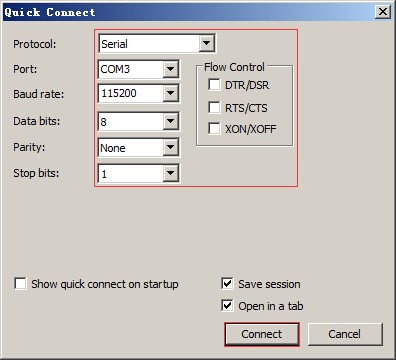
串口终端工具配置
- 通过Windows的设备管理器找到计算机上我们使用端口号。
- 配置串口终端工具的各参数。
- SecureCRT & USB串口3 示例配置如下:
- SecureCRT & USB串口3 示例配置如下:

网线的连接
将网线一端插入开发板的RGMII(开发板正面图的图示”ETH1”),网线另一端插入计算机的网口。
USB下载线的连接
将USB线一端连接到开发板的OTG(开发板正面图的图示”USBOTG”),另外一端插入计算机的USB接口。
连接电源线
将电源线一端连接到开发板的5V power input(开发板正面图的图示”DC_IN”),一端连接电源插座。
开发板的启动
在“开发板与计算机的连接”中按照顺序进行操作后,我们的开发板与计算机的连接已经完成了。要使开发板启动,我们需要为开发板上电。
为开发板上电
将开发板电源开关(开发板正面图的图示“PWR_SWITCH”)按到闭合状态(—:闭合,O:断开)。
观察启动状况
U-boot启动动态
会看到液晶屏被点亮,并显示 Freescale 与 明远智睿 的LOGO。
串口终端动态
会看到计算机的串口终端有开发板启动过程中输出的启动过程信息。
内核启动动态 (kernel booting dynamics)
内核启动到一定阶段后,在液晶屏上会看到小企鹅。
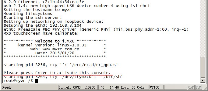
系统动态
1)Linux系统
- 系统启动完成后,在液晶屏上会保持小企鹅的显示。
- 串口输出信息会提示用户按下“Enter” ,这时候按下计算机上的“Enter”即可进入系统。
- 示例如下:
- 示例如下:

2)Linux QT系统
系统启动完成后,开发板会运行一个QT的示例程序,在液晶屏上可以看到QT示例程序的运行。
3)Ubuntu系统
系统启动完成后,在液晶屏上可以看到Ubuntu系统界面。