“MYZR-IMX8M-MB300 hardware introduction”的版本间的差异
(创建页面,内容为“<div> = '''Interface overview''' = ---- == ''''IMX8M-EK300 Front view''' == 642px == ''''IMX8M-EK300 Rear view''' == 文件:IMX...”) |
小 (Admin移动页面MY-IMX8M-MB300 hardware introduction至MYZR-IMX8M-MB300 hardware introduction,不留重定向) |
(没有差异)
| |
2020年10月22日 (四) 16:11的最新版本
目录
- 1 Interface overview
- 2 Interface function
- 2.1 WIFI、BT antenna
- 2.2 TFcard
- 2.3 Debug serial port
- 2.4 MIPI_DSI interface
- 2.5 MIPI_CSI1 interface
- 2.6 MIPI_CSI2 interface
- 2.7 PCIe 1x interface
- 2.8 Audio interface
- 2.9 JTAG interface
- 2.10 HDMI interface
- 2.11 BOOT MODE switch
- 2.12 BOOT CFG switch
- 2.13 Reset switch
- 2.14 Mini-PCIe/4G &SIM card
- 2.15 fan interface
- 2.16 Extension IO interface
- 2.17 Master power supply switch
- 2.18 Master power supply Enter
- 2.19 Bootloader interface
- 2.20 USB Extended serial port RS-485&RS-232
- 2.21 USB expansion dual USB HOST
- 2.22 Ethernet interface
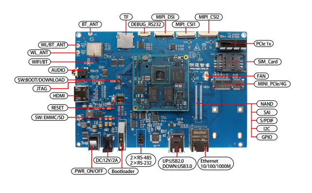
Interface overview
'IMX8M-EK300 Front view
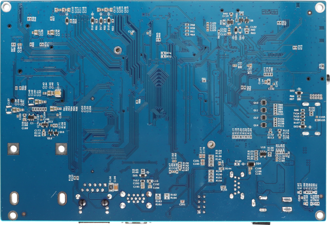
'IMX8M-EK300 Rear view
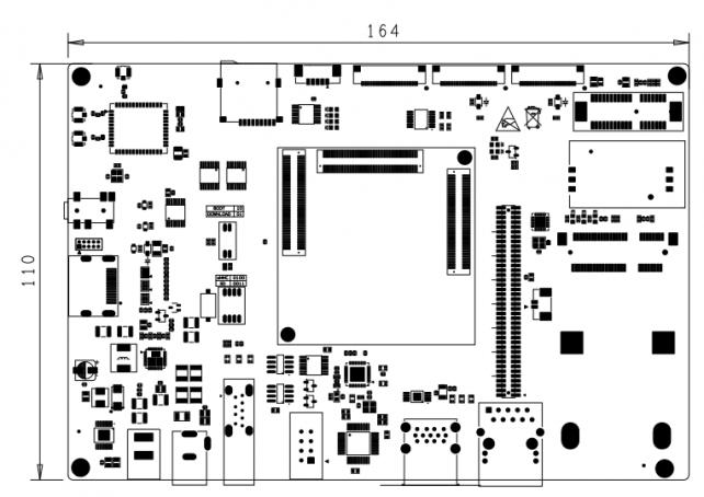
'IMX8M-EK300 Dimensions
Interface function
WIFI、BT antenna
Silk screen:WIFI_ANT、WIFI/BT_ANT、BT_ANT
The pins and signals are defined as follows:


TFcard
Silk screen:J5
The pins and signals are defined as follows:

Debug serial port
Silk screen:J1
The pins and signals are defined as follows:
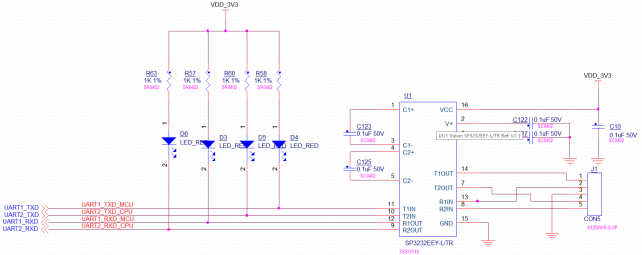
| Used pins | Features |
| UART1_TXD | MCUDebug serial data output |
| UART2_TXD | CPUDebug serial data output |
| UART1_RXD | MCUDebug serial data reception |
| UART2_RXD | CPUDebug serial data reception |
MIPI_DSI interface
Silk screen:J2
The pins and signals are defined as follows:
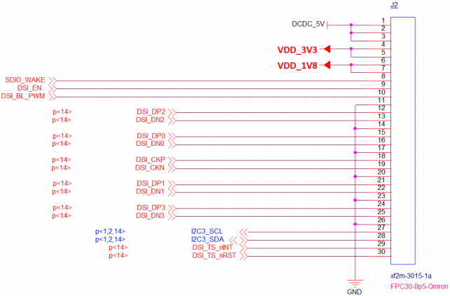
| Pin | signal | description | Pin | signal | description |
| J2-1 | DCDC_5V | 5V Output | J2-16 | DSI_DN0 | DSI Differential data 0 |
| J2-2 | J2-17 | GND | DGND | ||
| J2-3 | J2-18 | DSI_CKP | DSI Differential clock | ||
| J2-4 | VDD_3V3 | 3.3V Output | J2-19 | DSI_CKN | DSI Differential clock |
| J2-5 | J2-20 | GND | DGND | ||
| J2-6 | VDD_1V8 | 1.8V Output | J2-21 | DSI_DP1 | DSI Differential data 1 |
| J2-7 | J2-22 | DSI_DN1 | DSI Differential data 1 | ||
| J2-8 | SDIO_WAKE | GPIO control | J2-23 | GND | DGND |
| J2-9 | DSI_EN | GPIO control | J2-24 | DSI_DP3 | DSI Differential data 3 |
| J2-10 | DSI_BL_PWM | GPIO control | J2-25 | DSI_DN3 | DSI Differential data 3 |
| J2-11 | GND | DGND | J2-26 | GND | DGND |
| J2-12 | DSI_DP2 | DSI Differential data 2 | J2-27 | I2C3_SCL | touch I2Csignal |
| J2-13 | DSI_DN2 | DSI Differential data 2 | J2-28 | I2C3_SDA | touch I2Csignal |
| J2-14 | GND | DGND | J2-29 | DSI_TS_nINT | GPIO control |
| J2-15 | DSI_DP0 | DSI Differential data 0 | J2-30 | DSI_TS_nRST | GPIO control |
MIPI_CSI1 interface
Silk screen:J3
The pins and signals are defined as follows:

| Pin | signal | description | Pin | signal | description |
| J3-1 | DCDC_5V | 5V Output | J3-16 | CSI_P1_DP3 | CSI Differential data 3 |
| J3-2 | J3-17 | CSI_P1_DN3 | CSI Differential data 3 | ||
| J3-3 | VDD_1V8 | 1.8V Enter | J3-18 | GND | DGND |
| J3-4 | J3-19 | CSI_P1_DP2 | CSI Differential data 2 | ||
| J3-5 | VDD_3V3 | 3.3V Enter | J3-20 | CSI_P1_DN2 | CSI Differential data 2 |
| J3-6 | J3-21 | GND | DGND | ||
| J3-7 | GND | DGND | J3-22 | CSI_P1_DP1 | CSI Differential data 1 |
| J3-8 | GND | DGND | J3-23 | CSI_P1_DN1 | CSI Differential data 1 |
| J3-9 | I2C1_SDA_1V8 | I2Csignal,1.8V | J3-24 | GND | DGND |
| J3-10 | I2C1_SCL_1V8 | I2Csignal,1.8V | J3-25 | CSI_P1_CKP | CSI Differential clock |
| J3-11 | CSI_nRST | GPIO control | J3-26 | CSI_P1_CKN | CSI Differential clock |
| J3-12 | CSI_P1_PWDN | GPIO control | J3-27 | GND | DGND |
| J3-13 | GND | DGND | J3-28 | CSI_P1_DP0 | CSI Differential data 0 |
| J3-14 | CSI1_CLK | CSI clock | J3-29 | CSI_P1_DN0 | CSI Differential data 0 |
| J3-15 | GND | DGND | J3-30 | GND | DGND |
MIPI_CSI2 interface
Silk screen:J4
The pins and signals are defined as follows:
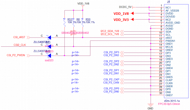
| Pin | signal | description | Pin | signal | description |
| J4-1 | DCDC_5V | 5V Output | J4-16 | CSI_P2_DP3 | CSI Differential data 3 |
| J4-2 | J4-17 | CSI_P2_DN3 | CSI Differential data 3 | ||
| J4-3 | VDD_1V8 | 1.8V Enter | J4-18 | GND | DGND |
| J4-4 | J4-19 | CSI_P2_DP2 | CSI Differential data 2 | ||
| J4-5 | VDD_3V3 | 3.3V Enter | J4-20 | CSI_P2_DN2 | CSI Differential data 2 |
| J4-6 | J4-21 | GND | DGND | ||
| J4-7 | GND | DGND | J4-22 | CSI_P2_DP1 | CSI Differential data 1 |
| J4-8 | GND | DGND | J4-23 | CSI_P2_DN1 | CSI Differential data 1 |
| J4-9 | I2C2_SDA_1V8 | I2Csignal,1.8V | J4-24 | GND | DGND |
| J4-10 | I2C1_SCL_1V8 | I2Csignal,1.8V | J4-25 | CSI_P2_CKP | CSI Differential clock |
| J4-11 | CSI_nRST | GPIO control | J4-26 | CSI_P2_CKN | CSI Differential clock |
| J4-12 | CSI_P2_PWDN | GPIO control | J4-27 | GND | DGND |
| J4-13 | GND | DGND | J4-28 | CSI_P2_DP0 | CSI Differential data 0 |
| J4-14 | CSI2_CLK | CSI clock | J4-29 | CSI_P2_DN0 | CSI Differential data 0 |
| J4-15 | GND | DGND | J4-30 | GND | DGND |
PCIe 1x interface
Silk screen:J6
The pins and signals are defined as follows:
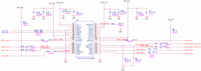
| Pin | signal | description | Pin | signal | description |
| J6-1B | VPCIe_12V | 12V power supply | J6-1A | GND | DGND |
| J6-2B | J6-2A | VPCIe_12V | 12V power supply | ||
| J6-3B | NC | J6-3A | VPCIe_12V | 12V power supply | |
| J6-4B | GND | DGND | J6-4A | GND | DGND |
| J6-5B | I2C2_SCL | I2Csignal | J6-5A | NC | |
| J6-6B | I2C2_SDA | I2Csignal | J6-6A | NC | |
| J6-7B | GND | DGND | J6-7A | NC | |
| J6-8B | VDD_3V3 | 3.3V power supply | J6-8A | NC | |
| J6-9B | NC | J6-9A | VDD_3V3 | 3.3V power supply | |
| J6-10B | VDD_3V3 | 3.3V power supply | J6-10A | VDD_3V3 | 3.3V power supply |
| J6-11B | GPIO1_IO04 | GPIO control | J6-11A | SAI2_RXC | GPIO control |
| J6-12B | NC | J6-12A | GND | DGND | |
| J6-13B | GND | DGND | J6-13A | PCIE1_REF_CLKP_CN | PCIE reference clock |
| J6-14B | PCIE1_TXP | PCIE data Output | J6-14A | PCIE1_REF_CLKN_CN | PCIE reference clock |
| J6-15B | PCIE1_TXN | PCIE data Output | J6-15A | GND | DGND |
| J6-16B | GND | DGND | J6-16A | PCIE1_RXP | PCIE data receive |
| J6-17B | SAI2_RXD | GPIO control | J6-17A | PCIE1_RXN | PCIE data receive |
| J6-18B | GND | DGND | J6-18A | GND | DGND |
Audio interface
Silk screen:P1
The pins and signals are defined as follows:

| Used pins | Features |
| SAI2_MCLK | Master clock |
| SAI2_TXC | Digital audio bit clock |
| SAI2_TXFS | SAI2_TXFS |
| SAI2_TXD | Digital audio data Output |
| AUD_nMUTE | Mute enable |
JTAG interface
Silk screen:J10
The pins and signals are defined as follows:
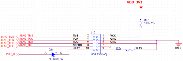
| Pin | signal | description | Pin | signal | description |
| J10-2 | JTAG_TMS | JTAG Mode selection | J10-1 | VDD_3V3 | 3.3V power supply |
| J10-4 | JTAG_TCK | JTAG clock Enter | J10-3 | GND | DGND |
| J10-6 | JTAG_TDO | JTAG data Output | J10-5 | GND | DGND |
| J10-8 | JTAG_TDI | JTAG data Enter | J10-7 | VNC | |
| J10-10 | POR_B | Reset | J10-9 | GND | DGND |
HDMI interface
Silk screen:J11
The pins and signals are defined as follows:
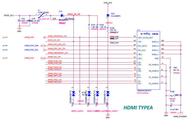
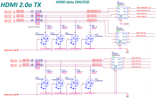
| Used pins | Features | Used pins | Features |
| HDMI_AUXP | Auxiliary Features interface | HDMI_TXN2 | HDMI Differential data 2 |
| HDMI_AUXN | Auxiliary Features interface | HDMI_TXP1 | HDMI Differential data 1 |
| HDMI_TXP0 | HDMI Differential data 0 | HDMI_TXN1 | HDMI Differential data 1 |
| HDMI_TXN0 | HDMI Differential data 0 | HDMI_DDC_SDA | DDC datasignal |
| HDMI_CLKP | HDMI Differential clock | HDMI_DDC_SCL | DDC clock signal |
| HDMI_CLKN | HDMI Differential clock | HDMI_HPD | Hot plug detection |
| HDMI_TXP2 | HDMI Differential data 2 | HDMI_CEC | HDMI Consumer Electronics Agreement |
BOOT MODE switch
Silk screen:SW1
The pins and signals are defined as follows:
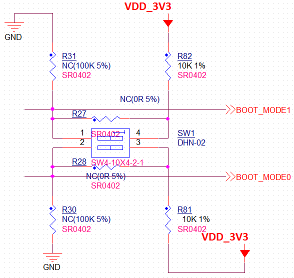
| mode control | 1bit | 2bit |
| Flash mode | 0 | 1 |
| start up mode | 1 | 0 |
BOOT CFG switch
Silk screen:SW3
The pins and signals are defined as follows:
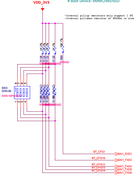
| start up control | 1bit | 2bit | 3bit | 4bit |
| eMMC | 0 | 0 | 1 | 0 |
| SD | 1 | 1 | 0 | 0 |
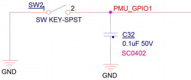
Reset switch
Silk screen:SW2
Features:Press Reset
The pins and signals are defined as follows:
Mini-PCIe/4G &SIM card
| name | Silk screen | interface Attributes |
| mini-PCIE/4G | J14 | miniPCIE Standard interface,PCIe 2.0 Standard ,Support 4G module |
| SIM card Deck | CON1 | 4G SIM card Deck |
The pins and signals are defined as follows:
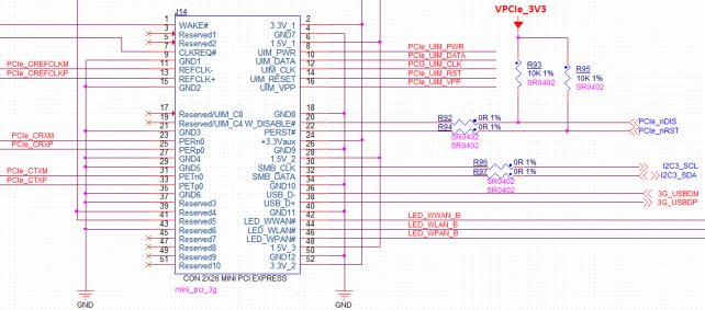

| Used pins | Features | Used pins | Features |
| PCIe_nWAKE | PCIE wake | PCIE2_TXP | PCIE Differential data Output |
| PCIe_nCLKREQ | PCIE clock request | PCIe_nDIS | PCIE Forbid control |
| PCIE2_REF_CLKN_CN | PCIE difference reference clock | PCIe_nRST | PCIE bus Reset |
| PCIE2_REF_CLKP_CN | PCIE difference reference clock | I2C3_SCL | I2C clock |
| PCIE2_RXN | PCIE Differential data Enter | I2C3_SDA | I2C data |
| PCIE2_RXP | PCIE Differential data Enter | 3G_USBDM | USB differencesignal |
| PCIE2_TXN | PCIE Differential data Output | 3G_USBDP | USB differencesignal |
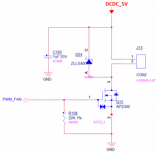
fan interface
Silk screen:J13
The pins and signals are defined as follows:
Extension IO interface
Silk screen:J12
The pins and signals are defined as follows:
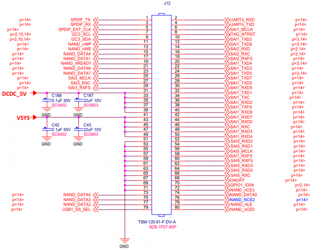
| Pin | signal | Pin | signal |
| J12-1 | SPDIF_TX | J12-2 | UART4_RXD |
| J12-3 | SPDIF_RX | J12-4 | UART4_TXD |
| J12-5 | SPDIF_EXT_CLK | J12-6 | SAI1_MCLK |
| J12-7 | I2C3_SCL | J12-8 | JTAG_NTRST |
| J12-9 | I2C3_SDA | J12-10 | SAI1_TXD2 |
| J12-11 | NAND_nWP | J12-12 | SAI1_TXD6 |
| J12-13 | NAND_nWE | J12-14 | SA12_RXD |
| J12-15 | NAND_DATA4 | J12-16 | SA12_RXC |
| J12-17 | NAND_DATA1 | J12-18 | SA12_RXFS |
| J12-19 | NAND_nREADY | J12-20 | SAI1_TXD4 |
| J12-21 | NAND_DATA6 | J12-22 | SAI1_TXD3 |
| J12-23 | NAND_DATA7 | J12-24 | SAI1_TXD5 |
| J12-25 | SAI3_MCLK | J12-26 | SAI1_TXD7 |
| J12-27 | SAI3_RXC | J12-28 | SAI1_TXD0 |
| J12-29 | SAI3_RXFS | J12-30 | SAI1_RXD5 |
| J12-31 | DCDC_5V | J12-32 | SAI1_TXD1 |
| J12-33 | J12-34 | SAI1_TXC | |
| J12-35 | J12-36 | SAI1_RXD2 | |
| J12-37 | J12-38 | SAI1_TXFS | |
| J12-39 | J12-40 | SAI1_RXD6 | |
| J12-41 | VSYS | J12-42 | SAI1_RXD7 |
| J12-43 | J12-44 | SAI1_RXD0 | |
| J12-45 | J12-46 | SAI1_RXC | |
| J12-47 | J12-48 | SAI1_RXD3 | |
| J12-49 | J12-50 | SAI1_RXD4 | |
| J12-51 | GND | J12-52 | SAI5_RXD2 |
| J12-53 | J12-54 | SAI5_RXD1 | |
| J12-55 | J12-56 | SAI5_MCLK | |
| J12-57 | J12-58 | SAI1_RXFS | |
| J12-59 | J12-60 | SAI5_RXFS | |
| J12-61 | J12-62 | SAI5_RXD3 | |
| J12-63 | J12-64 | SAI5_RXD0 | |
| J12-65 | J12-66 | SAI5_RXC | |
| J12-67 | J12-68 | ONOFF | |
| J12-69 | J12-70 | GPIO1_IO04 | |
| J12-71 | J12-72 | NAND_nCE3 | |
| J12-73 | NAND_DATA5 | J12-74 | NAND_DATAO |
| J12-75 | NAND_DATA3 | J12-76 | NAND NCE2 |
| J12-77 | NAND_DATA2 | J12-78 | NAND_ALE |
| J12-79 | USB1_SS_SEL | J12-80 | NAND_nCE0 |
Master power supply switch
Silk screen:SW4
The pins and signals are defined as follows:
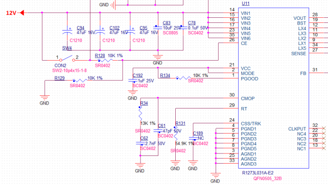
Master power supply Enter
Silk screen:J19
interface Attributes:Internal positive and negative socket, 12V voltage
The pins and signals are defined as follows:

Bootloader interface
Silk screen:J15
The pins and signals are defined as follows:
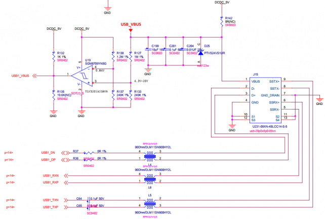
| Used pins | Features |
| USB1_VBUS | VBUS Detection |
| USB1_DN | USB Differential data |
| USB1_DP | USB Differential data |
| USB1_RXN | USB Differential data Enter |
| USB1_RXP | USB Differential data Enter |
| USB1_TXN | USB Differential data Output |
| USB1_TXP | USB Differential data Output |
USB Extended serial port RS-485&RS-232
Silk screen:J17
The pins and signals are defined as follows:
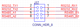
| Pin | signal | Pin | signal |
| RS232_TX1 | RS-232signal Output | RS232_RX1 | RS-232signal receive |
| RS232_TX2 | RS-232signal Output | RS232_RX2 | RS-233signal receive |
| RS482_A1 | RS-485 differencesignal+ | RS482_B1 | RS-485 differencesignal- |
| RS482_A2 | RS-485 differencesignal+ | RS482_B2 | RS-485 differencesignal- |
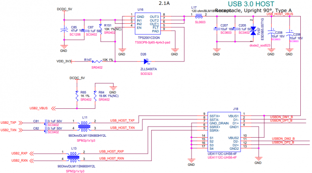
USB expansion dual USB HOST
Silk screen:J18
interface Attributes:USB2 extension USB2.0&USB3.0,USB TYPE-A interface
The pins and signals are defined as follows:
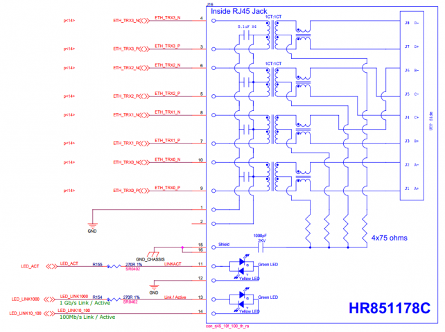
Ethernet interface
Silk screen:J16
interface Attributes:RGMII,stand by 10/100/1000M
The pins and signals are defined as follows:
