MYZR-SAMA5 Linux-3.18 测试手册
目录
- 1 = 测试前的准备(preparation before test) =
- 2 = 测试项目(test item) =
- 3 网口测试(lan port test)
- 4 2packets transmitted, 2 packets received, 0% packet loss
- 5 USB测试(USB test)
- 6 SD卡接口测试(SD card interface test)
- 7 LED(GPIO)测试(LED(GPIO)test)
- 8 串口测试(serial port test)
- 9 RTC测试(RTC test)
- 10 SPI测试 (SPI test)
- 11 CAN接口测试 (CAN infterface test)
- 12 WIFI测试(WIFI test)
= 测试前的准备(preparation before test) =
1)请按照《Linux快速启动手册》中的“Linux快速启动” -> “连接设备”进行连接。<br>
please refer to "connection of device"->"Linux fast boot" in 《Linux fast boot manual》 for the connection。
2)请按照《Linux快速启动手册》中的“Linux快速启动” -> “启动设备”进行启动。
please refer to "booting device" ->"Linux fast boot" in 《Linux fast boot manual》 for the booting。
= 测试项目(test item) =
网口测试(lan port test)
MY-SAMA5-EK200支持双网口(1个百兆网口,一个千兆网口)。
MY-SAMA5-EK200 support dual lan port(one Mbps ethernet lan port,one Gbps ethernet lan port)
测试说明(test instruction)
- 第1个以太网口位置底板正面“J3”,第2个以太网口位置底板正面“J2”。
MY-SAMA5-EK200 support dual lan port(one Mbps ethernet lan port,one Gbps ethernet lan port)
测试方法(test method)
1) 测试第1个以太网口(百兆网口)
test the first ethernet lan port(Mbps ethernet lan port)
- 连接网线:用网络连接评估板“J3”与计算机网口
connect lan line:connect “J3”on evaluation board with computer lan port through network
- 设置计算机IP:设置计算机网口IP为192.168.18.18
set computer IP:set computer lan port IP as 192.168.18.18

- 设置评估板IP:
set IP of evaluation board
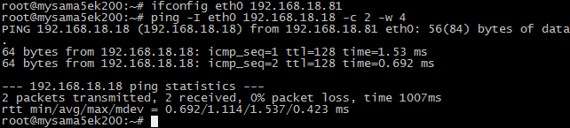
# ifconfig eth0 192.168.18.81 # configure the eth0
# ifconfig eth1 down
- 执行测试命令:
execute test command
# ping 192.168.18.18 -c 2 -w 4 # send ICMP to HOST
- 观察测试结果:系统会输出类似如下信息:
observe test result:system will output information like below:
--- 192.168.18.18 ping statistics ---
2packets transmitted, 2 packets received, 0% packet loss
- 测试结果:“0% packet loss”表示测试通过
test result:“0% packet loss”represent test passing - 附图
figure
2) 测试第2个以太网口(千兆网口)
test the second ethernet lan port - 连接网线:拔下第1个网口的网线接口插入到评估板“J2”,网线另一端保持与计算机网口相连。
connect lan line:take out lan line from the first lan port then plug in “J2”on evaluation board,another end of lan line is kept in connection with lan port of computer - 设置计算机IP:设置计算机网口IP为192.168.18.18(如已经设置过可执行下一步骤)。
set computer IP:set computer lan port IP as 192.168.18.18(if the setting was already done then go direclty into next step) - 设置第2个网口IP:
set the second lan port IP:
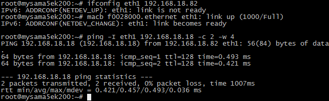
# ifconfig eth1 192.168.18.82 # configure the eth1
# ifconfig eth0 down
设置后系统会输出第2个网口的工作状态信息,类似如下:
after the setting system will output working condition of the second lan port, as below
macb f0028000.ethernet eth1: link up (1000/Full) - 执行测试命令:
run test command
# ping 192.168.18.18 -c 2 -w 4 # send ICMP to HOST - 观察测试结果:系统会输出类似如下信息:
observe test result:system will output the following message:
--- 192.168.18.18 ping statistics ---

2packets transmitted, 2 packets received, 0% packet loss
- 测试结果:“0% packet loss”表示测试通过
test result:“0% packet loss”represent test passing - 附图
figures

USB测试(USB test)
测试说明(test instruction)
MY-IMX6-EK200有2个USB HOST接口,位于底板正面“J8”。
MY-IMX6-EK200 has two USB HOST ports,in“J8”in top view of base board
测试方法(test method)
1) 开始测试
start test
将USB设备插入底板USB接口,系统会输出类似如下信息:
plug USB device in USB port in base board,system will output the following message:
usb -.*: new high-speed USB device number * using atmel-ehci
……
2) 测试结束
complete test
将USB设备从底板拔出,系统会输出类似如下信息:
take out USB device from the base board,system will output the following message:
usb -.*: USB disconnect, device number *
附图(figures)

说明:在USB口上插拔U盘时,系统输出信息类似如下:
instruction:insert U disk in USB port, system will output information like below:
SD卡接口测试(SD card interface test)
测试说明(test instruction )
SD卡接口位于底板背面“J29”。
SD card interface is in“J29”in bottom view of base board。
开始测试(start test)
1) 往SD卡槽插入设备
insert device in SD card slot
插入SD卡到底板SD卡接口。系统输出以下信息(见附图)即表示SD接口正常:
insert SD card in SD card port in base board, system will output following message(see attached image),e.g.SD port is normal:
mmc*: new high speed SD card at address ****
……
2)从SD卡槽弹出设备
pop-up device from SD card slot
再次住SD卡槽按下SD卡,底板会弹出SD卡。系统输出以下信息(见附图)表示SD卡接口弹出正常:
press again SD card in SD card slot,base board will pop-up SD card。system will output following message(see attached image),e.g.function of SD card port pop-up is normal:
mmc*: card **** removed
3) 结束测试
complete test
SD卡弹出后拨出SD卡即结束测试。
take out SD card after SD card pop-up,to end the test。
附图(figures)

LED(GPIO)测试(LED(GPIO)test)
LED(GPIO)定义(LED(GPIO)definition)
在MY-SAMA5-EK200底板正面有4个LED,详细如下:
there are 4 LEDs on the base board of MY-SAMA5-EK200,details as below:
| 丝印 (silkscreen) |
CPU引脚 (CPU pin) |
LED属性 (LED property)
led-default测试(led-default test)led-default对应D12。系统启动完成后,该LED默认被点亮,通常可用作供电指示。就是说在用户没有控制该指示灯的情况下,亮表示设备通电(即电源工作正常)。当然,用户也可以控制该指示灯的亮灭,但这时候灯灭与电源是否工作不存在关联。 led-heartbeatled-heartbeat对应D13。系统启动后,该LED闪烁,该LED的状态可表示CPU的工作状态。闪烁表示CPU工作正常。常亮或常灭表示CPU工作不正常(即可能是CPU不工作了)。 led-gpio测试(led-gpio test)led-gpio对应D14。系统启动后,该LED默认保持常灭的状态。进入系统后,我们可通过指令来控制该LED的亮灭。 led-timer测试(led-timer test)led-timer对应D15。这主要演示GPIO作为timer信号。 串口测试(serial port test)MY-SAMA5-EK200评估板有6个串口,其中5个为用户串口,1个为调试串口(位于底板正面“P1”位置)。
在串口测试中我们测试5个用户串口。 测试说明(test instruction)
instruction of test method
instruction of test result 测试方法(test method)1)短接串口的收发引脚
download test application
add executable authority for the test program
specify serial port which need to be tested
execute test command RTC测试(RTC test)测试说明(test instruction)受快递运输影响,MY-SAMA5-EK200 评估板发货时不带电池。测试RTC前请自备纽扣电池并安装到底板背面“BT1”上(在丝印“RTC”旁边)。 due to restrictions in transportation,MY-SAMA5-EK200 evaluation board doesn't contatin battery in delivery。before RTC test please prepare button cell to install on “BT1”in bottom view of base board(beside silkscreened name of“RTC”) 测试方法(test method)1)断电重启设备,查看当前系统时间和硬件时间。 power off then reboot device,to check the current time of system and hardware。
command to check current system clock as below
message outputed by system as below: 2)查看当前RTC芯片时钟命令如下: command to check clock of RTC chip as below:
message outputed by system as below: 3)设置系统时钟,并同步到RTC芯片 set system clock and synchronously set to RTC chip)
command to set system clock as below: # date -s "2015-11-23 12:34:56"
command to write system clock into hardware as below: # hwclock –w power off and reboot evaluation board,to check current system clock and hardware clock) 请参考第1步 please refer to the first step SPI测试 (SPI test)MY-SAMA5-EK200上有一组SPI接口,在“J22”位置上。 测试说明(test instruction)SPI测试采用自发送(输出)自接收(输入)的方式。 测试方法(test method)1)短接SPI的收发引脚
download test application
add executable authority for the test program CAN接口测试 (CAN infterface test)测试说明(test instruction)CAN测试需要用到示波器,没有示波器的客户请跳过CAN测试。 测试方法(test method)1)配置CAN0 WIFI测试(WIFI test)1)在网盘“4_烧录支持/mysama5ek200_image”下载编译好的 WIFI 驱动模块“8188eu.ko”。 |


