MY-IMX6-EK140 Linux-3.14 测试手册
目录
[隐藏]- 1 测试前的准备(preparation before test)
- 2 测试项目(test item)
- 2.1 网口测试( test of network interface)
- 2.2 USB测试(USB test)
- 2.3 SD卡测试(SD card test)
- 2.4 标准GPIO测试(standard GPIO test)
- 2.5 GPIO-LED测试(GPIO-LED test)
- 2.6 串口测试(serial port test)
- 2.7 SPI测试(SPI test)
- 2.8 背光测试(test of backlight)
- 2.9 CAN接口测试 (CAN interface test)
- 2.10 RTC测试(RTC test)
- 2.11 WatchDog测试(WatchDog test)
测试前的准备(preparation before test)
1)请按照《Linux快速启动手册》中的“Linux快速启动” -> “连接设备”进行连接。
please follow the path of 《Linux fast boot manual》->“Linux fast boot” -> “connect device”for connection
2)请按照《Linux快速启动手册》中的“Linux快速启动” -> “启动设备”进行启动。
please follow the path of 《Linux fast boot manual》->“Linux fast boot” -> “boot device”for booting
测试项目(test item)
网口测试( test of network interface)
MY-IMX6-EK140支持一个百兆网口。
MY-IMX6-EK140 support one Mbps network interface
接口属性(interface property)
| 评估板型号 (evaluation board model) |
CPU接口 (CPU interface) |
系统接口 (system interface) |
接口丝印 (interface silk screen) |
|---|---|---|---|
| MY-IMX6-EK140 | ENET1 | eth0 | P1 |
测试方法(test method)
1) 配置计算机IP
configure computer IP
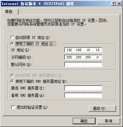
设置计算机有线网卡IP为192.168.18.18
set IP of cable network interface card for computer as 192.168.18.18

2) Eth0连接测试
Eth0 test for Wth0 connection
- 连接网线:将评估板“eth0”对应的接口与计算机有线网卡的接口用网线相连接
lan line connection:connect interface corresponding to “eth0”on evaluation board with interface of cable network interface card on computer through lan line
- 设置评估板IP:
set IP for evaluation board
# ifconfig eth0 192.168.18.36 # configure the eth0
- 执行测试命令:
execute test command
# ping 192.168.18.18 -c 2 -w 4 # send ICMP to HOST
- 观察测试结果:系统会输出类似如下信息:
view test result,you can see information outputed by system like below
--- 192.168.18.18 ping statistics ---
2packets transmitted, 2 packets received, 0% packet loss
- 测试结果:“0% packet loss”表示测试通过
test reuslt:“0% packet loss” represent passing of test
- 附图
USB测试(USB test)
接口属性(interface property)
| 评估板型号 (evaluation board model) |
CPU接口 (CPU interface) |
系统接口 (system interface) |
接口丝印 (interface silk screen) |
|---|---|---|---|
| MY-IMX6-EK140 | USB_OTG1 | USB OTG | J4 |
| USB_OTG2 | USB HOST | J7[…] |
USB OTG测试(USB OTG test)
1) 将MicroUSB转USB的转接线连接到USB1,系统会输出类似如下信息:
connect to USB1 with USB switch wiring from MicroUSB,system will output information like below.
ci_hdrc ci_hdrc.0: new USB bus registered, assigned bus number 2
ci_hdrc ci_hdrc.0: USB 2.0 started, EHCI 1.00
2) 连接USB设备。即:将U盘插入转接线上的USB口,系统会输出类似如下信息:
connect USB device,e.g insert U disk to USD port on the switch wiring,system will output information like below.
usb 2-1: new high-speed USB device number 12 using ci_hdrc
usb-storage 2-1:1.0: USB Mass Storage device detected
3) 拔出USB设备,系统会输出类似如下信息:
take out USB device,system will output information like below.
usb 2-1: USB disconnect, device number 12
4) 拔下USB转接线,系统会输出类似如下信息:
take out USB switch wiring,system will output information like below.
ci_hdrc ci_hdrc.0: remove, state 4
usb usb2: USB disconnect, device number 1
ci_hdrc ci_hdrc.0: USB bus 2 deregistered
USB HOST测试(USB HOST test)
MY-IMX6-EK140 的USB HOST是插座形式,如要测试HOST功能,需要把自备USB头,并且将插座上的USB HOST信号线连接到USB头,此操作请找自己的硬件工程师请求支持。
MY-IMX6-EK140 USB HOST is socket type,if need to test the function of HOST,need to connect signal line of USB HOST to the USB head self-prepared, the operation need an assistance from hardware engineer.
另外,请硬件工程师知晓,由于CPU的USB_VBUS供电能力不足,需要将“5V_core”与USB_VBUS相连。
Moreover,please let engineer know that power supply capability of CPU的USB_VBUS is not enough,so need to connect“5V_core”with USB_VBUS
附图(figure)
SD卡测试(SD card test)
接口属性(interface property)
| 评估板型号 (evaluation board model) |
CPU接口 (CPU interface) |
系统设备 (system device) |
接口丝印 (interface silk screen) |
|---|---|---|---|
| MY-IMX6-EK140 | SD1 | mmc0 | U15 |
测试说明(test instruction)
MY-IMX6-EK140的TF卡接口不支持热插拔。
MY-IMX6-EK140的TF card interface doesn't support hot plug
测试方法(test method)
1)为MY-IMX6-EK140断电。
power off MY-IMX6-EK140
2)将TF卡安装好板子的TF卡座上,并确认安装好。
install TF card in TF card holder,and confirm the installation ok
3)为MY-IMX6-EK140上电,待系统启动完成后进入系统。
power on MY-IMX6-EK140,enter the system after booting is finished
5)检查TF卡:
check TF card
# dmesg | grep "mmc0"
TF卡正常则可以看到类似如下信息:
if IF card is normal, then you can see information like below.
mmc0: host does not support reading read-only switch. assuming write-enable.
mmc0: new high speed SD card at address 0002
附图(figure)
标准GPIO测试(standard GPIO test)
接口属性(interface property)
| 评估板型号 (evaluation board model) |
CPU接口 (CPU interface) |
系统设备 (system device) |
信号名称 (name of signal) |
接口位置 (interface position) |
|---|---|---|---|---|
| MY-IMX6-EK140 | SNVS_TAMPER3 | gpio131 | SNVS_TAMPER3 | J7:31 |
| SNVS_TAMPER7 | gpio135 | SNVS_TAMPER7 | J7:32 |
测试说明(test instruction)
标准GPIO的测试以GPIO131为例,其它GPIO测试可参照GPIO131的测试方法。
take GPIO131 as an example of standard GPIO test,other GPIO tests refer to the test method of GPIO131
测试方法(test method)
1)设置需要测试的GPIO的IO序号
set IO order number of GPIO which need to be tested
# OUT_IO_NUMBER=131
2)导出GPIO
lead out GPIO
# echo ${OUT_IO_NUMBER} > /sys/class/gpio/export
3)设置GPIO方向
set direction for GPIO
# echo "out" > /sys/class/gpio/gpio${OUT_IO_NUMBER}/direction
4)控制输出电平
control output electrical level
# echo 0 > /sys/class/gpio/gpio${OUT_IO_NUMBER}/value
执行命令后即可用万用表检测到对应的引脚为低电平。
leads detected by multimeter accordingly will be low electrical level after execution of command
# echo 1 > /sys/class/gpio/gpio${OUT_IO_NUMBER}/value
执行命令后即可用万用表检测到对应的引脚为高电平。
leads detected by multimeter accordingly will be high electrical level after execution of command
附图(figure)
GPIO-LED测试(GPIO-LED test)
接口属性(interface property)
| 评估板型号 (evaluation board model) |
SOC接口 (SOC interface) |
系统设备 (system device) |
接口位置 (interface position) |
|---|---|---|---|
| MY-IMX6-EK140 | SNVS_TAMPER4 | default | D1 |
| SNVS_TAMPER1 | Heartbeat | D2 | |
| SNVS_TAMPER8 | led-timer | D4 | |
| SNVS_TAMPER5 | leds-gpio | D5 |
GPIO-LED(Default)测试(GPIO-LED(Default)test)
Default的实现是初始触发状态为on,即系统启动后开发板上对应接口位置的LED常亮。
Default is fullfilled with original trigger state as on, e.g LED on the corresponding port of development board is always bright after booting of system
Default可以通过brightness控制。
default is controled through brightness
往brightness写0即把该IO拉低,LED常灭。
writing 0 to brightness will drop down IO,LED is always off
# echo 0 > /sys/class/leds/default/brightness
往brightness写1即把该IO拉高,LED常亮。
writing 1 to brightness will drop up IO,LED is always bright
# echo 1 > /sys/class/leds/default/brightness
GPIO-LED(Heartbeat)测试(GPIO-LED(Heartbeat) test)
系统启动完成后,可以在开发板上看到Heartbeat对应接口位置的LED在闪烁。
LED on interface correponding to hearbeat on devleopment board will flash after system boot is over
GPIO-LED(Timer)测试(GPIO-LED(Timer)test)
系统启动完成后,可以在开发板上看到led-timer对应接口位置的LED在闪烁:
LED on interface correponding to led-tiomer on devleopment board will flash after system boot is over
通过delay_off、delay_on来控制高低电平持续的时间。
control duration of high low eletrical level through delay_off、delay_on
# echo 500 > /sys/class/leds/led-timer/delay_off
# echo 1000 > /sys/class/leds/led-timer/delay_on
再看led-timer对应的LED灯,在闪烁过程中可以发现亮的时间比灭的时间长。
view LED corresponding to led-time,you can find that time period of lighting is longer than being off in cycle of flash
GPIO-LED(leds-gpio)测试(GPIO-LED(leds-gpio)test)
GPIO的测试可以使用跟default类似的方法:
GPIO test can adopt the similar way for default test
往brightness写1即把该IO拉高,LED常亮。
writting 1 to brightness will drop up IO,LED is always bright
# echo 1 > /sys/class/leds/leds-gpio/brightness
往brightness写0即把该IO拉低,LED常灭。
writting 0 to brightness will drop down IO, LED is always off
# echo 0 > /sys/class/leds/leds-gpio/brightness
串口测试(serial port test)
MY-IMX6-EK140共8个串口,其中1个调试串口,7个用户串口。
MY-IMX6-EK140 has 8 serial port, one is debug serial port, the other 7 are user serial ports
串口属性(property of serial port)
| 评估板型号 (evaluation board model) |
SOC接口 (SOC interface) |
系统设备 (system device) |
信号名称 (name of signal) |
接口位置 (interface position) |
|---|---|---|---|---|
| MY-IMX6-EK140 | UART1 | ttymxc0 | UART1_* | J7 |
| UART2 | ttymxc1 | UART2_* | J1 | |
| UART3 | ttymxc2 | UART3_* | J1 | |
| UART4 | ttymxc3 | UART4_* | J1 | |
| UART5 | ttymxc4 | UART5_* | J1 | |
| UART6 | ttymxc5 | UART6_* | J1 | |
| UART7 | ttymxc6 | UART7_* | J1 | |
| UART8 | ttymxc7 | UART8_* | J1 |
串口测试(interface)
1)测试说明
test intruction
测试的应用程序会配置串口为loopback模式,并进行loopback测试。测试中我们以UART2(ttymxc1)为例。
the test application will configure serial port as mode of loopback,and conduct loopback test.we only take UART2(ttymxc1)as an example in the tes
2)执行测试命令
execute test command
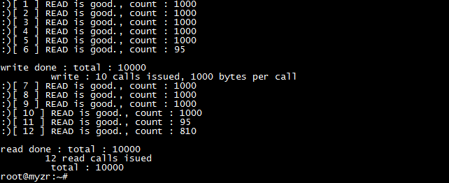
# /unit_tests/mxc_uart_stress_test.out /dev/ttymxc1 115200 D L 10 1000 O
终端显示“Hit enter to start Loopback”后按下PC上的回车键。
press Enter key on PC when “Hit enter to start Loopback” is shown on termina
测试命令说明:
intruction of test command
/unit_tests/mxc_uart_stress_test.out:测试程序文件
/unit_tests/mxc_uart_stress_test.out:file of test program
/dev/ttymxc1:需要进行测试的串口设备文件
115200:串口测试的波特率
115200:baud rate for serial port
D:关闭流控(loopback测试不能使用流控)
D:close fluid control
L:loopback 测试
L:loopback test
10:测试次数
times of number of test
1000:测试的数据长度(字节)
leghth of data of test
O:显示测试log
display test log
附图(figure)
SPI测试(SPI test)
接口属性(interface property)
测试需要用到SPI接口的MISO和MOSI管脚,在下表中列出。
pin of MISO and MOSI need to be used for the test,listed as blow.
| 评估板型号 (evaluation board model) |
SOC接口 (SOC interface) |
系统设备 (system device) |
信号名称 (name of signal) |
接口位置 (interface position) |
|---|---|---|---|---|
| MY-IMX6-EK140 | ECSPI1 | spidev0.0 | ECSPI1_* | J7:[23,25,…] |
| ECSPI2 | spidev1.0 | ECSPI2_* | J7:[24,26,…] |
说明(instruction)
采用SPI自发送(输出)自接收(输入)的方式。
adopt way of SPI self-sending(output) self-receiving(input)
注意:测试需要短接评估板的管脚,如果不确定自己能正确短接的请找硬件工程师支持,否则可能会损坏评估板。
note:need a short connection of pins of evaluation board,if you are not sure of how to do that, please ask engineers for support,otherwise it may cause a damage for evaluation board.
测试方法(test method)
1)执行测试
execute test
- SPI1测试
SPI1 test
短接SPI1的MISO和MISO管脚。
short connect pins of MISO and MISO of SPI1
# ~/my-demo/linux-3.14.52/spidev_test.out -D /dev/spidev0.0 -s 1000000
- SPI2测试
SPI2 test
短接SPI2的MISO和MISO管脚。
short connect pins of MISO and MISO of SPI2
# ~/my-demo/linux-3.14.52/spidev_test.out -D /dev/spidev1.0 -s 1000000
2)测试结果
test result
如果SPI正常,在终端上会看到如下字符:
if SPI is normal, you can see the following charaters on the terminal
FF FF FF FF FF FF
40 00 00 00 00 95
FF FF FF FF FF FF
FF FF FF FF FF FF
FF FF FF FF FF FF
DE AD BE EF BA AD
F0 0D
附图(figure)
背光测试(test of backlight)
接口属性(interface property)
| 评估板型号 (evaluation board model) |
SOC接口 (SOC interface) |
系统设备 (system device) |
信号名称 (name of signal) |
接口位置 (interface position) |
|---|---|---|---|---|
| MY-IMX6-EK140 | PWM4 | backlight.8 | PWM4 | -- |
测试方法(test method)
1)查看背光可支持的最大亮度等级
check the maximum brightness grade supported by backlight
# cat /sys/devices/soc0/backlight.8/backlight/backlight.8/max_brightness
2)查看当前背光亮度等级
check current brightness grade of backlight
# cat /sys/devices/soc0/backlight.8/backlight/backlight.8/brightness
3)控制背光亮度等级(下面命令将背光等级调到3)
control brightness grade of backlight
# echo 3 > /sys/devices/soc0/backlight.8/backlight/backlight.8/brightness
可以看到显示屏的亮度发生了变化。
you can see the change of brightness of screen
附图(figure)
CAN接口测试 (CAN interface test)
接口属性(interface property)
| 评估板型号 (evaluation board model) |
SOC接口 (SOC interface) |
系统设备 (system device) |
信号名称 (name of signal) |
接口位置 (interface position) |
|---|---|---|---|---|
| MY-IMX6-EK140 | CAN1 | can0 | CAN1_* | J1 |
| CAN2 | can1 | CAN2_* | J1 |
测试说明(test instruction)
MY-IMX6-EK140从CPU上引出了CAN信号,但是在EK140上不带CAN收发芯片,所以不能直接测试CAN。如果需要测试CAN的收发,需要外接CAN收发芯片或CAN收发器。
MY-IMX6-EK140 lead out CAN signal from CPU,but there is not CAN receiving chip on EK140 ,so CAN can't be tested directly。if want to test the transceiver of CAN,need to connect externally CAN transceiving chip or CAN transceiver.
RTC测试(RTC test)
测试说明(test instruction)
   1)受快递运输影响,开发板发货时不带电池。测试RTC前请自备纽扣电池并安装到评估板上。

   due to restrictions in transportation,evaluation board doesn't contatin battery in delivery。before RTC test please prepare button cell to install on the evaluation board

   2)MY-IMX6-MB140不带RTC,RTC在MY-IMX6-EXT140上,没有EXT140的客户可跳过此测试。

   MY-IMX6-MB140 doesn't carry RTC,RTC is on MY-IMX6-EXT140,user who doesn't have EXT140 can skip this test

   3)MY-IMX6-EK140的电池座在底板背面。

   battery holder of MY-IMX6-EK140 is on rear view of base board
测试方法(test method)
   1)断电重启设备,系统启动完成后查看当前系统时间和硬件时间。

   power off then reboot device, view the time of system and hardware after system booting is over
# date
# hwclock
   2)设置系统时钟,并同步到RTC芯片

   set system clock and synchronously set to RTC chip.

   # hwclock –w

   3)断电重启评估板,查看当前系统时钟和硬件时钟

   power off and reboot evaluation board,check current system clock and hardware clock

   # date

   # hwclock
附图(figure)
WatchDog测试(WatchDog test)
测试说明(test instruction)
WatchDog测试包括2项:一项是复位测试,一项是喂狗测试。
WatchDog test includes two items:one is reset test,the other is feed dog test
复位测试(re-set test)
1)测试说明
test instruction
复位测试将启动WatchDog,但是并不喂狗,超时后系统将会复位。
reset test will boot WatchDog,but doesn't feed dog,system will reset after 60 seconds
2)执行测试
execute test
# /unit_tests/wdt_driver_test.out 2 4 1
   3)测试结果

   test result

   运行测试命令后等待几秒,WatchDog超时,系统被复位。将会在终端看到系统重新启动输出的信息。
wait for a few seconds after running of test command,WatchDog timeout,system is resetted。you can see information outputed by system rebooting on terminal

喂狗测试 (test of feeding dog)
1)测试说明
test instuction
喂狗测试将启动WatchDog,并且每2秒钟进行1次喂狗,系统将不会因为WatchDog超时而复位。
feeding dog test will boot WatchDog,and feed dog every 2 seconds,system won't reset because of WatchDog timeout
2)执行测试
execute test
- 启动WatchDog
start WatchDog
# /unit_tests/wdt_driver_test.out 4 2 1 &
- 查看当前时间
3)验证
verify
- 查看当前时间
view current time
经过几分钟之后,系统依然没有复位。我们再查看当前时间。
after a new minutes,system hasn't reseted yet. we re-check current time
# date
- 停止喂狗
stop dog feeding
这时我们终止Watchdog测试程序,这样就没有程序进行喂狗了,系统将会在超时时间(这里是4秒)内复位。
then we stop test program for Watchdog,in this case there is not program to feed dgo,system will reset in timeout(here is 4 seconds)
# pkill wdt_driver_test

</div>


