MYZR-IMX6-MB140-MINI Hardware Introduction
来自明远智睿的wiki
目录
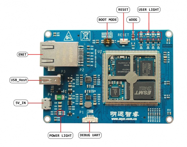
[隐藏]Interface overview
Front view
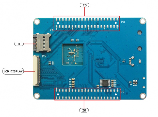
Rear view
graphic module
| NO. | Interface | Function | Interface form | Silk screen |
|---|---|---|---|---|
| 1 | 5V_IN | Power IN & MFG Tool Download port | Micro USB | P4 |
| 2 | USB_Host | USB 2.0 | USB_A | P3 |
| 3 | ENET | 10/100-Mbps ethernet | RJ-45 | P2 |
| 4 | DEBUG UART | Debug serial port | Single row pin(4 pins) | P1 |
| 5 | BOOT MODE | Boot mode option | Dial switch(2bit) | SW2 |
| 6 | RESET & WDOG | reset button & WatchDog | Key(2 pins) | SW1 |
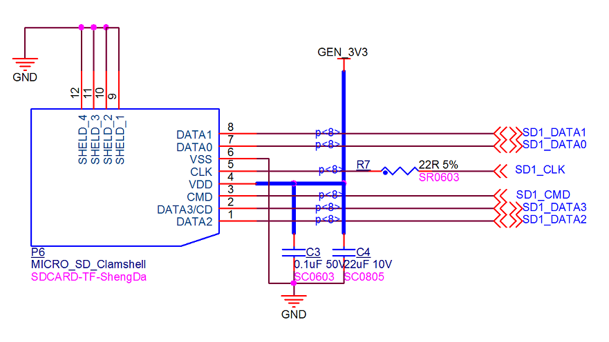
| 7 | TF | TF card | TF booth(flip-type) | P6 |
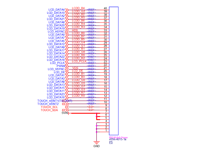
| 8 | LCD DISPLAY | LCD display interface | FPC socket(flip-type,40 Pins) | P5 |
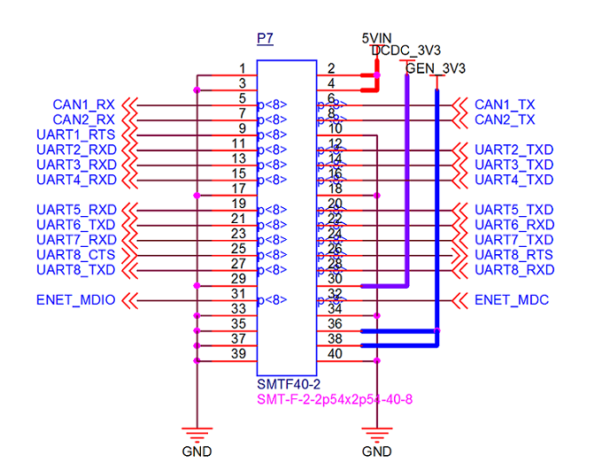
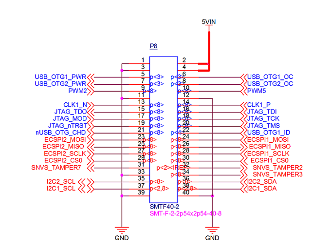
| 9 | IO | Function socket | Double row socket(40 Pins) | P7、P8 |
| 10 | USER LIGHT | User LED light | LED light (4 units) | D1~4 |
| 11 | POWER LIGHT | Power indication light | LED light (2 units) | D5~6 |
Interface function
5V_IN
| NO. | Interface | Function | Interface form | Silk screen |
|---|---|---|---|---|
| 1 | 5V_IN | Power IN & MFG Tool Download port | Micro USB | P4 |
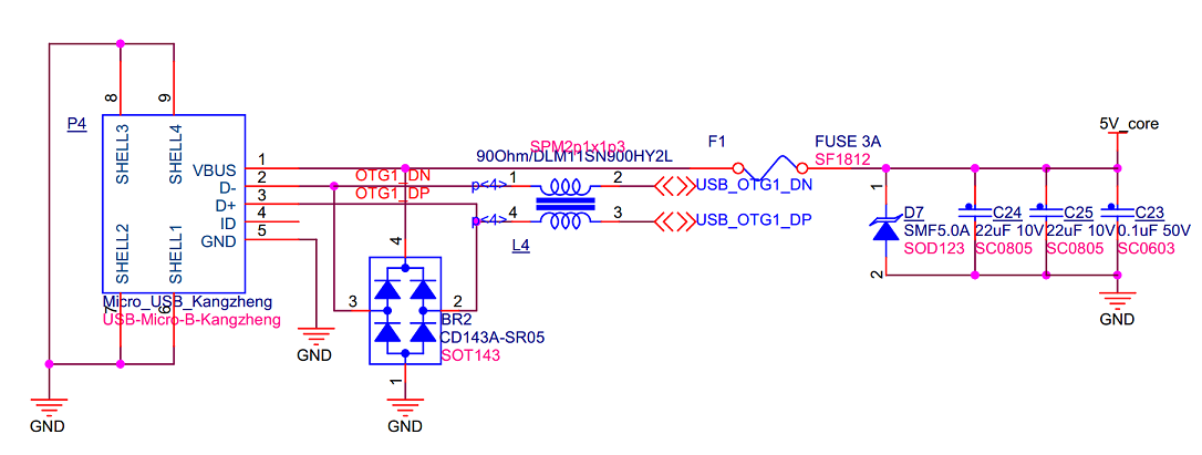
- Schematic and signal
| Interface order number | Name of function signal | Pin used |
|---|---|---|
| 1 | VBUS | USB_OTG1_VBUS |
| 2 | D- | USB_OTG1_DN |
| 3 | D+ | USB_OTG1_DP |
| 4 | ID | NC |
| 5 | GND | GND |
USB_Host
- The standard input voltage is 5V for MYZR-IMX6-MB140,and It Use Micro USB as power port.
- Need to pay attention to the USB cable's power supply, it is recommended to use the original USB cable.
| NO. | Interface | Function | Interface form | Silk screen |
|---|---|---|---|---|
| 2 | USB_Host | USB 2.0 | USB_A | P3 |
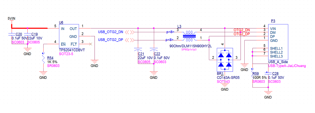
- Schematic and signal
| Interface order number | Name of function signal | Pin used |
|---|---|---|
| 1 | GND | GND |
| 2 | DP | USB_OTG1_DP |
| 3 | DN | USB_OTG1_DN |
| 4 | VIN | 5VIN |
ENET
| NO. | Interface | Function | Interface form | Silk screen |
|---|---|---|---|---|
| 3 | ENET | 10/100-Mbps ethernet | RJ-45 | P2 |
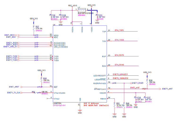
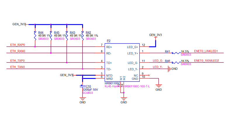
- Schematic and signal
- Interface map and signal
DEBUG UART
| NO. | Interface | Function | Interface form | Silk screen |
|---|---|---|---|---|
| 4 | DEBUG UART | Debug serial port | Single row pin(4 pins) | P1 |
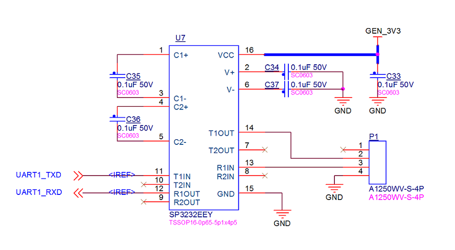
- Schematic and signal
| Interface order number | Pin function |
|---|---|
| 1 | NC |
| 2 | 232_TX |
| 3 | 232_RX |
| 4 | GND |
BOOT MODE
| NO. | Interface | Function | Interface form | Silk screen |
|---|---|---|---|---|
| 5 | BOOT MODE | Bboot mode option | Dial switch(2 bit) | SW2 |
- Schematic and boot device option
| BMODE[1:0] | BOOT TYPE |
|---|---|
| 01 | Serial Downloader |
| 10 | Internal Boot (Development) |
RESET & WDOG
| NO. | Interface | Function | Interface form | Silk screen |
|---|---|---|---|---|
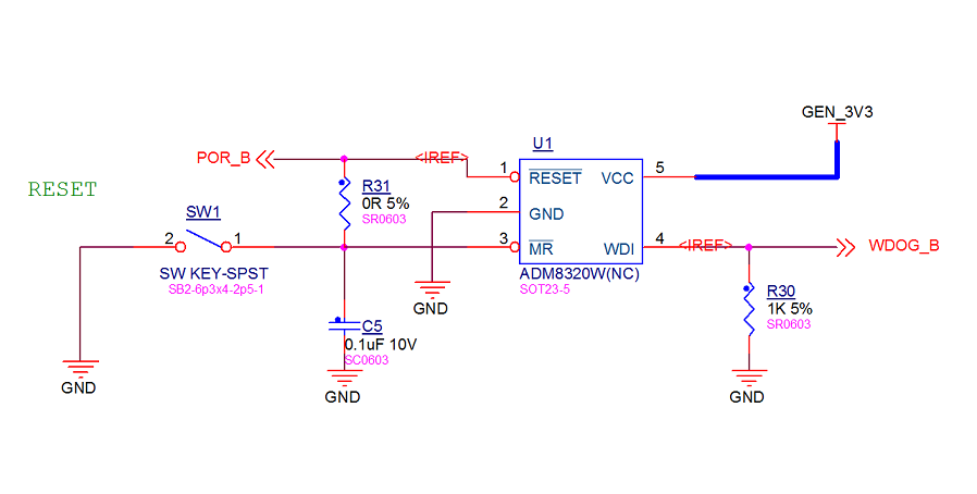
| 6 | RESET & WDOG | Reset button & WatchDog | Key(2 pins) | SW1 |
- Schematic and signal
TF
| NO. | Interface | Function | Interface form | Silk screen |
|---|---|---|---|---|
| 7 | TF | TF卡 (TF card) |
TF socket(flip type) | P6 |
- Schematic and signal
LCD DISPLAY()
| NO. | Interface | Function | Interface form | Silk screen |
|---|---|---|---|---|
| 8 | LCD DISPLAY | LCD display interface | EPC socket(flip type,40 pins) | P5 |
- Schematic and signal
| Interface order number | Pin function | Signal used |
|---|---|---|
| 1~4 | GND | GND |
| 5~7 | PWR | 5VIN |
| 8 | I2C_SDA | TOUCH_SDA |
| 9 | I2C_SCL | TOUCH_SCL |
| 10 | IO | TOUCH_nEINT2 |
| 11 | IO | TOUCH_nEINT1(TSC2007) |
| 12、13、24、25、27、34、35、37 | LCD_R[0:7] | LCD_DATA[16:23] |
| 14、15、16、17、26、28、29、39 | LCD_G[0:7] | LCD_DATA[8:15] |
| 18、19、30、31、32、36、38、40 | LCD_B[0:7] | LCD_DATA[0:7] |
| 20 | Data Input Enable | LCD_DE |
| 21 | Vertical Sync Input | LCD_VSYNC |
| 22 | Backlight brightness | PWM4 |
| 23 | Sample clock | LCD_PCLK |
| 33 | Horizontal Sync Input | LCD_HSYNC |
IO
| NO. | Interface | Function | Interface form | Silk screen |
|---|---|---|---|---|
| 9 | IO | Function socket | Double row socket(40 Pins) | P7、P8 |
- Schematic and signal
| P7 | P8 | |||||||
|---|---|---|---|---|---|---|---|---|
| 1 | 5VIN | 2 | 5VIN | 1 | 5VIN | 2 | 5VIN | |
| 3 | 5VIN | 4 | 5VIN | 3 | 5VIN | 4 | 5VIN | |
| 5 | CAN1_RX | 6 | CAN1_TX | 5 | USB_OTG1_PWR | 6 | USB_OTG1_OC | |
| 7 | CAN2_RX | 8 | CAN2_TX | 7 | USB_OTG2_PWR | 8 | USB_OTG2_OC | |
| 9 | UART1_RTS | 10 | GND | 9 | PWM2 | 10 | PWM5 | |
| 11 | UART2_RXD | 12 | UART2_TXD | 11 | GND | 12 | GND | |
| 13 | UART3_RXD | 14 | UART3_TXD | 13 | CLK1_N | 14 | CLK1_P | |
| 15 | UART4_RXD | 16 | UART4_TXD | 15 | JTAG_TDO | 16 | JTAG_TDI | |
| 17 | GND | 18 | GND | 17 | JTAG_MOD | 18 | JTAG_TCK | |
| 19 | UART5_RXD | 20 | UART5_TXD | 19 | JTAG_nTRST | 20 | JTAG_TMS | |
| 21 | UART6_TXD | 22 | UART6_RXD | 21 | nUSB_OTG_CHD | 22 | USB_OTG1_ID | |
| 23 | UART7_RXD | 24 | UART7_TXD | 23 | ECSPI2_MOSI | 24 | ECSPI1_MOSI | |
| 25 | UART8_CTS | 26 | UART8_RTS | 25 | ECSPI2_MISO | 26 | ECSPI1_MISO | |
| 27 | UART8_TXD | 28 | UART8_RXD | 27 | ECSPI2_SCLK | 28 | ECSPI1_SCLK | |
| 29 | GND | 30 | DCDC_3V3 | 29 | ECSPI2_CS0 | 30 | ECSPI1_CS0 | |
| 31 | ENET_MDIO | 32 | ENET_MDC | 31 | SNVS_TAMPER7 | 32 | SNVS_TAMPER2 | |
| 33 | GND | 34 | GND | 33 | GND | 34 | SNVS_TAMPER3 | |
| 35 | GND | 36 | GEN_3V3 | 35 | I2C2_SCL | 36 | I2C2_SDA | |
| 37 | GND | 38 | GEN_3V3 | 37 | I2C1_SCL | 38 | I2C1_SDA | |
| 39 | GND | 40 | GND | 39 | GND | 40 | GND | |
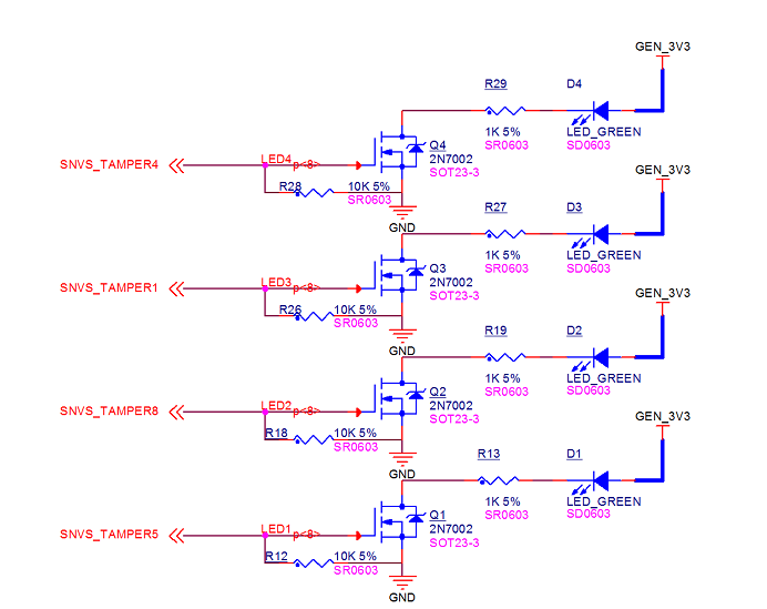
USER LIGHT
| NO. | Interface | Function | Interface form | Silk screen |
|---|---|---|---|---|
| 11 | USER LIGHT | User LED | LEDLIGHT (4 unit) | D1~4 |
- Schematic and signal
| Interface order number | Pin function | Signal used |
|---|---|---|
| D1 | LED | SNVS_TAMPER5 |
| D2 | LED | SNVS_TAMPER8 |
| D3 | LED | SNVS_TAMPER1 |
| D4 | LED | SNVS_TAMPER4 |
POWER LIGHT
| NO. | Interface | Function | Interface form | Silk screen |
|---|---|---|---|---|
| 12 | POWER LIGHT | Power indicator light | LED light(2 units) | D5~6 |
- Schematic and signal
| Silk screen | Function |
|---|---|
| D7 | Red LED power indicator light |
| D8 | Green LED power indicator light |
